Log #18 · Sep 27, 2026
Why You Need a Motor Driver (L298N vs TB6612)
What an H-bridge does, why Arduino pins cannot drive motors directly, and how to wire and code the L298N and TB6612FNG drivers.
An Arduino pin can safely supply about 20 mA. A small robot gear motor needs 150 mA just to spin and can pull over 1 A when it starts or stalls. Connect one directly and you risk destroying the pin, or the whole microcontroller. A motor driver sits in between: the Arduino sends tiny control signals, and the driver switches the heavy motor current from a separate battery. This guide explains how drivers work and compares the two most popular boards.
Three problems a driver solves
- Current: the driver's transistors handle amps; the Arduino only supplies milliamps.
- Voltage: motors often run at 6–12 V, above the Arduino's 5 V logic.
- Direction: to reverse a DC motor you must reverse the voltage across it, which needs a special circuit called an H-bridge.
How an H-bridge works
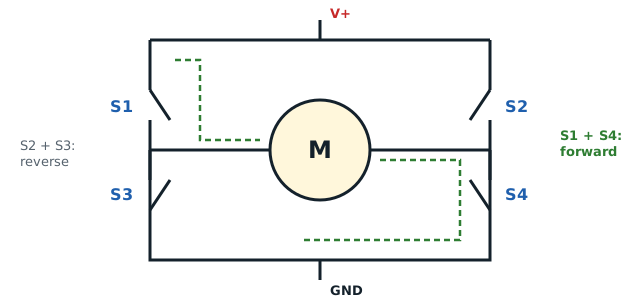
An H-bridge has four switches arranged around the motor like the letter H. Closing opposite corners sends current through the motor one way; closing the other pair sends it the other way.
| Switches closed | Result |
|---|---|
| S1 + S4 | Motor spins forward |
| S2 + S3 | Motor spins in reverse |
| None | Motor coasts to a stop |
| S3 + S4 (both low side) | Motor brakes |
| S1 + S3 or S2 + S4 | Short circuit! |
Driver chips handle this logic internally so you cannot accidentally short the supply. You just set two direction pins and a PWM speed pin.
The L298N: the classic
The red L298N module appears in nearly every robot car kit. It drives two DC motors (or one stepper), handles up to about 2 A per channel, and accepts motor supplies from 5 to 35 V.
Its big weakness is efficiency. It uses older bipolar transistors that drop roughly 2 V or more at typical currents. Feed it a 7.4 V battery and your motors may only see around 5 V, with the rest turned into heat, hence the large heatsink.
Wiring for one motor:
| L298N pin | Connect to |
|---|---|
| 12V (motor supply) | Battery + (7–12 V) |
| GND | Battery − and Arduino GND |
| ENA | Arduino pin 5 (PWM), remove the jumper |
| IN1 | Arduino pin 7 |
| IN2 | Arduino pin 8 |
| OUT1, OUT2 | Motor wires |
The onboard 5 V regulator can power the Arduino when the jumper is fitted and the supply is 12 V or less.
The TB6612FNG: the efficient choice
The TB6612FNG is a small breakout using MOSFETs. It drives two motors at 1.2 A continuous (3.2 A peak) per channel, with motor voltages up to 13.5 V. Its voltage drop is only a few tenths of a volt, so motors get nearly the full battery voltage and the board stays cool. It needs a separate logic supply (VCC, 2.7–5.5 V) and has a STBY pin that must be HIGH to enable the outputs.
| L298N | TB6612FNG | |
|---|---|---|
| Channels | 2 | 2 |
| Continuous current | about 2 A | 1.2 A |
| Motor voltage | 5–35 V | 4.5–13.5 V |
| Voltage lost | around 2 V or more | around 0.1–0.5 V |
| Size | Large, heatsink | Small, breadboard-friendly |
| Best for | Bigger 12 V motors, kits | Small robots on batteries |
For the yellow TT motors used in most small robots, the TB6612FNG is the better driver: more speed from the same battery and much longer battery life.
Code: speed and direction
This works with either driver. For the TB6612, also set STBY HIGH in setup().
const int PWM_A = 5;   // ENA on L298N, PWMA on TB6612
const int IN1 = 7;     // AIN1 on TB6612
const int IN2 = 8;     // AIN2 on TB6612

void setup() {
  pinMode(PWM_A, OUTPUT);
  pinMode(IN1, OUTPUT);
  pinMode(IN2, OUTPUT);
}

// speed from -255 (full reverse) to 255 (full forward)
void motorA(int speed) {
  digitalWrite(IN1, speed > 0);
  digitalWrite(IN2, speed < 0);
  analogWrite(PWM_A, abs(speed));
}

void loop() {
  motorA(200);  delay(2000);   // forward
  motorA(0);    delay(500);    // stop
  motorA(-200); delay(2000);   // reverse
  motorA(0);    delay(500);
}
Writing a single motorA(speed) function keeps the rest of your program clean. The obstacle-avoiding robot builds directly on it for two motors.
Common mistakes
- No common ground. The battery ground, driver ground and Arduino ground must all connect, or the control signals mean nothing.
- Leaving the ENA jumper on the L298N. The motor then runs at full speed and ignores your PWM.
- Forgetting STBY on the TB6612. Everything is wired, code runs, motors do nothing.
- Weak batteries. A 9 V battery cannot supply motor current for long. Use AA packs or Li-ion cells, as compared in our battery guide.
- Motors spin the wrong way. Swap the two motor wires at the driver instead of rewriting code.
For the bigger picture on keeping motors and electronics on healthy power, read how to power an Arduino project.
— TheSolderBench · found a mistake? tell me