Log #36 · Sep 27, 2026
Build an Obstacle-Avoiding Robot
A complete build with parts list, wiring table and full Arduino code for a two-wheel robot that scans with an ultrasonic sensor and steers around obstacles.
This robot drives forward until it sees something in its way, stops, looks left and right with its ultrasonic "eyes", and turns toward whichever side has more space. It combines four things covered elsewhere on this site: a distance sensor, a servo, a motor driver and battery power. If you have followed those guides, this project is where they come together.
Parts list
| Part | Quantity | Notes |
|---|---|---|
| 2WD robot chassis with TT motors and caster | 1 | See the chassis guide |
| Arduino Uno or Nano | 1 | |
| TB6612FNG motor driver | 1 | An L298N also works |
| HC-SR04 ultrasonic sensor | 1 | |
| SG90 micro servo + sensor bracket | 1 | Turns the sensor left and right |
| 2 × 18650 holder with switch | 1 | Or 6 × AA holder |
| 2 × 18650 Li-ion cells | 2 | Protected cells recommended |
| Mini breadboard, jumper wires | ||
| 470 µF capacitor | 1 | Across the servo supply |
How it works
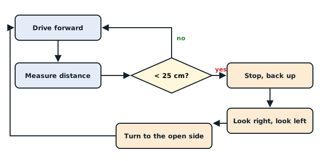
- Point the sensor straight ahead and drive forward.
- Measure the distance every 60 ms.
- If something is closer than 25 cm, stop and back up briefly.
- Turn the servo to look right, then left, measuring each side.
- Turn toward the side with more room, then continue.
Wiring
| From | To |
|---|---|
| Battery + (via switch) | TB6612 VM and Arduino VIN |
| Battery − | TB6612 GND and Arduino GND |
| Arduino 5V | TB6612 VCC, HC-SR04 VCC, servo red |
| Arduino GND | HC-SR04 GND, servo brown |
| TB6612 STBY | Arduino pin 4 |
| TB6612 PWMA, AIN1, AIN2 | Arduino pins 5, 7, 8 (left motor) |
| TB6612 PWMB, BIN1, BIN2 | Arduino pins 6, 12, 13 (right motor) |
| TB6612 A01, A02 / B01, B02 | Left motor / right motor |
| HC-SR04 TRIG, ECHO | Arduino pins 9, 10 |
| Servo signal (orange) | Arduino pin 11 |
The SG90 is small enough to run from the Arduino's 5 V rail, especially with the 470 µF capacitor across its power wires. If the board resets when the servo moves, give the servo its own 5 V regulator, as explained in how to power an Arduino project.
Note: on the Uno, the Servo library disables PWM on pins 9 and 10, which is why the motor PWM signals use pins 5 and 6 and the servo signal uses pin 11.
The code
#include <Servo.h>

const int STBY = 4;
const int PWMA = 5, AIN1 = 7, AIN2 = 8;     // left motor
const int PWMB = 6, BIN1 = 12, BIN2 = 13;   // right motor
const int TRIG = 9, ECHO = 10;
const int SERVO_PIN = 11;

const int SPEED = 170;
const int STOP_CM = 25;

Servo neck;

void setMotor(int pwm, int in1, int in2, int speed) {
  digitalWrite(in1, speed > 0);
  digitalWrite(in2, speed < 0);
  analogWrite(pwm, min(abs(speed), 255));
}

void drive(int left, int right) {
  setMotor(PWMA, AIN1, AIN2, left);
  setMotor(PWMB, BIN1, BIN2, right);
}

float distanceCm() {
  digitalWrite(TRIG, LOW);  delayMicroseconds(2);
  digitalWrite(TRIG, HIGH); delayMicroseconds(10);
  digitalWrite(TRIG, LOW);
  unsigned long us = pulseIn(ECHO, HIGH, 30000);
  return us == 0 ? 400 : us / 58.0;        // no echo: treat as open space
}

float lookAt(int angle) {
  neck.write(angle);
  delay(350);                               // let the servo arrive
  float d = distanceCm();
  delay(60);
  return d;
}

void setup() {
  int outs[] = {STBY, PWMA, AIN1, AIN2, PWMB, BIN1, BIN2, TRIG};
  for (int p : outs) pinMode(p, OUTPUT);
  pinMode(ECHO, INPUT);
  digitalWrite(STBY, HIGH);                 // enable the TB6612
  neck.attach(SERVO_PIN);
  neck.write(90);
  delay(1000);
}

void loop() {
  float ahead = distanceCm();

  if (ahead > STOP_CM) {
    drive(SPEED, SPEED);
    delay(60);
    return;
  }

  drive(0, 0);                              // obstacle: stop
  delay(150);
  drive(-SPEED, -SPEED);                    // back up a little
  delay(250);
  drive(0, 0);

  float right = lookAt(20);
  float left  = lookAt(160);
  neck.write(90);
  delay(250);

  if (left > right) drive(-SPEED, SPEED);   // spin left
  else              drive(SPEED, -SPEED);   // spin right
  delay(350);                               // roughly a 90 degree turn
  drive(0, 0);
  delay(100);
}
Each piece comes from an earlier guide: distanceCm() from the HC-SR04 guide, setMotor() from the motor driver guide and the servo sweep from controlling a servo.
Testing step by step
Test each subsystem before running the full program:
- Motors: lift the robot so the wheels spin freely and run
drive(150, 150). Both wheels should spin forward. If one spins backwards, swap its two motor wires. - Sensor: print
distanceCm()to the Serial Monitor and move your hand in front of it. - Servo: run
lookAt(20)andlookAt(160)and check the sensor faces right and left. Swap the angles in the code if your servo is mounted the other way. - Full program: place the robot on the floor in an open area with a few boxes as obstacles.
Tuning
- Turns too little or too much: adjust the
delay(350)after the spin. Turning time depends on battery voltage and floor friction. - Hits obstacles: raise
STOP_CMto 30–35, or lowerSPEED. - Misses thin chair legs: ultrasonic sensors struggle with thin or angled objects; add a second sensor or IR proximity sensors at the corners.
- Drives in a curve: the two motors run at slightly different speeds. Reduce the faster side's speed a little, or learn how to correct it automatically in PID control explained.
Ideas to extend it
- Add a buzzer that beeps when an obstacle is detected.
- Add IR line sensors and switch between obstacle mode and line-following mode with a button.
- Replace the fixed turn delay with wheel encoders for precise 90° turns.
— TheSolderBench · found a mistake? tell me