Log #27 · Sep 27, 2026
PID Control Explained Without Heavy Math
What the P, I and D terms actually do, shown with a robot that follows a line, plus Arduino code and a step-by-step tuning method.
PID control is behind cruise control in cars, temperature control in 3D printers, drones that hover in place and robots that follow lines smoothly. The name sounds intimidating, but the idea fits in one sentence: measure how wrong you are, and correct based on how wrong you are now, how wrong you have been, and how fast it is changing. This guide explains each part with a robot example, gives you working code and shows a practical tuning routine.
The setup: error
Every control loop starts with an error, the difference between what you want and what you measure.
error = setpoint − measurement
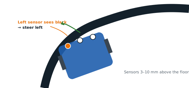
For a line-following robot, the setpoint is "line centered" (0), and the measurement is the line's position under the sensors, from −100 to +100. For a robot keeping 20 cm from a wall with an ultrasonic sensor, the setpoint is 20 and the measurement is the distance reading.
The controller's job is to turn that error into an action, such as steering or motor speed.
P: react to the present
The proportional term corrects in proportion to the current error:
P = Kp × error
Far off the line? Steer hard. Slightly off? Steer gently. Proportional control alone is a huge improvement over simple on/off steering.
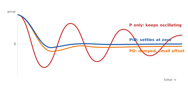
Its weakness: if Kp is high enough to react quickly, the robot overshoots, swings past the line, overcorrects and oscillates. If Kp is low, it is sluggish. And in some systems P alone leaves a small permanent error, because as the error shrinks, so does the correction.
D: react to the trend
The derivative term looks at how fast the error is changing:
D = Kd × (error − previous error)
When the robot is swinging back toward the line quickly, the error is shrinking fast, so the D term pushes against the motion, like a brake. It damps the oscillation that P causes. Think of it as anticipation: "I'm approaching the target quickly, ease off now."
Too much Kd makes the robot twitchy, because it amplifies sensor noise.
I: remember the past
The integral term adds up the error over time:
I = Ki × (sum of all past errors)
If the robot keeps sitting slightly to one side, perhaps because one motor is weaker, the sum keeps growing until the I term is large enough to push it back to center. It removes steady offsets that P and D cannot.
Too much Ki causes slow, large oscillations. The sum can also grow huge while the robot is stuck or lifted off the ground, a problem called integral windup, so real code limits it.
Putting it together
correction = Kp × error + Ki × integral + Kd × derivative
Arduino code
This loop runs a PID controller for a line follower. readError() returns the line position and drive() sets the two motors, as in the line-follower guide.
float Kp = 0.6, Ki = 0.0, Kd = 2.5;
const int BASE = 150;

float integral = 0;
int lastError = 0;

void loop() {
  int error = readError();                 // -100 .. +100

  integral += error;
  integral = constrain(integral, -1000, 1000);   // anti-windup
  int derivative = error - lastError;

  float correction = Kp * error + Ki * integral + Kd * derivative;
  lastError = error;

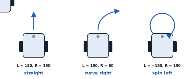
  int left  = constrain(BASE + correction, -255, 255);
  int right = constrain(BASE - correction, -255, 255);
  drive(left, right);

  delay(5);   // keep the loop timing steady
}
Two practical details matter here. First, the loop runs at a fixed rate. The D and I terms depend on time, so if the loop speed changes, the tuning changes too. Second, constrain() keeps the integral and the motor values within safe limits.
Tuning, step by step
There is math for calculating gains, but for hobby robots hands-on tuning works well:
- Set Ki and Kd to zero. Start with a small Kp.
- Increase Kp until the robot follows the line but oscillates noticeably. Then reduce it by about a third.
- Increase Kd gradually until the oscillation dies down and the robot tracks smoothly. If it starts to shake or buzz, back off.
- Add a small Ki only if the robot consistently sits to one side on straights. Many line followers never need it.
- Raise the base speed and repeat small adjustments. Faster robots usually need more Kd.
Change one value at a time, and write down what you tried. A potentiometer wired to an analog pin, as in our servo knob example, makes live tuning much faster than re-uploading code.
Symptoms and fixes
| What you see | Likely cause | Try |
|---|---|---|
| Slow, lazy corrections, loses curves | Kp too low | Raise Kp |
| Fast side-to-side wobble | Kp too high or Kd too low | Lower Kp or raise Kd |
| Jittery, twitchy motion | Kd too high or noisy sensor | Lower Kd, filter readings |
| Always slightly off-center | Steady offset | Add a small Ki |
| Slow, big swings that grow | Ki too high | Lower Ki, check anti-windup |
Beyond line following
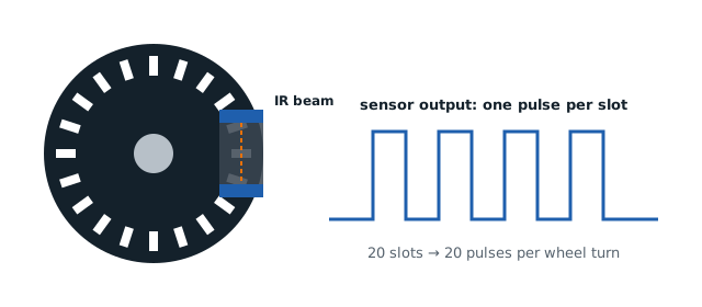
The same code structure controls a motor's speed using an encoder, holds a balancing robot upright, keeps a heater at a set temperature, or keeps a DC motor turning at a steady speed under changing load. Once you have tuned one PID loop by hand, the others feel familiar.
— TheSolderBench · found a mistake? tell me