Log #29 · Sep 27, 2026
Adding Wheel Encoders to a Robot
How optical and magnetic encoders count wheel rotation, how to read them with interrupts, and how to measure distance and drive straight.
Two identical-looking motors never spin at exactly the same speed, so a robot told to drive straight slowly curves. Timed turns are just as unreliable: a 350 ms spin gives 90° on a fresh battery and 70° on a tired one. Wheel encoders fix both problems by measuring how far each wheel actually turned. This guide explains how they work, how to read them with interrupts and how to use the counts to measure distance and drive straight.
What an encoder measures
An encoder produces a pulse each time the wheel or motor shaft turns a small, fixed amount. Count the pulses and you know the rotation; count them over time and you know the speed.
The number of pulses per revolution is called resolution, often written as PPR (pulses per revolution) or CPR (counts per revolution).
Common encoder types
Optical slot encoders
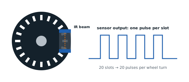
Many 2WD kits include a slotted disc that mounts on the motor shaft and an optical interrupter module (often based on a sensor like the H206 or FC-03). An infrared beam shines through the slots; each time a solid section blocks it, the output changes.
- A typical kit disc has 20 slots, so 20 pulses per wheel revolution.
- They are cheap and easy, but they only give speed, not direction.
Magnetic quadrature encoders
Gear motors such as the N20 or JGA25 are available with a small magnet disc and two Hall-effect sensors on the back of the motor. They produce two signals, A and B, shifted by a quarter cycle. Which one changes first tells you the direction. Because they sit on the motor shaft before the gearbox, the counts per wheel revolution are high: a 7-pulse motor encoder with a 1:30 gearbox gives 210 pulses per wheel revolution, or more when you count every edge.
Reading pulses with interrupts
You could check the encoder pin in loop(), but if the loop is busy printing or waiting for a sensor, you miss pulses. The reliable way is an interrupt: the hardware pauses your program the instant the pin changes, runs a tiny function, then returns.
On an Uno or Nano, pins 2 and 3 support external interrupts, which is perfect for one encoder per wheel.
volatile long leftCount = 0;
volatile long rightCount = 0;

void leftPulse()  { leftCount++; }
void rightPulse() { rightCount++; }

void setup() {
  Serial.begin(115200);
  pinMode(2, INPUT_PULLUP);
  pinMode(3, INPUT_PULLUP);
  attachInterrupt(digitalPinToInterrupt(2), leftPulse,  RISING);
  attachInterrupt(digitalPinToInterrupt(3), rightPulse, RISING);
}

void loop() {
  noInterrupts();                 // copy safely while counts may change
  long l = leftCount, r = rightCount;
  interrupts();
  Serial.print("L:"); Serial.print(l);
  Serial.print(" R:"); Serial.println(r);
  delay(200);
}
Three rules for interrupt code:
- Mark shared variables
volatile, so the compiler always reads the latest value. - Keep the interrupt function tiny. No printing, no delays.
- Copy multi-byte counters with interrupts briefly disabled, as above, so you never read a half-updated number.
Use the Serial Monitor to spin each wheel by hand and confirm the counts rise.
From counts to distance
For a wheel of diameter D, one revolution moves the robot π × D.
distance per pulse = π × D ÷ pulses per revolution
With 65 mm wheels and a 20-slot disc:
π × 65 ÷ 20 ≈ 10.2 mm per pulse
So to drive 1 meter, run the motors until the count reaches about 1000 ÷ 10.2 ≈ 98 pulses. Resolution matters here: with 20 pulses per revolution, you can only measure distance in 10 mm steps.
Accurate turns
For a differential-drive robot spinning on the spot, each wheel travels along a circle whose diameter is the track width W, the distance between the wheels. For a 90° turn each wheel moves a quarter of that circle:
arc = π × W ÷ 4
With W = 130 mm, that is about 102 mm, or 10 pulses per wheel with our disc. Replace the timed turn in the obstacle-avoiding robot with "spin until both wheels reach 10 pulses", and turns stay consistent as the battery drains.
Driving straight
To keep the robot straight, compare the two counts and slow down the wheel that is ahead:
const int BASE = 160;
const float K = 4.0;

void loop() {
  noInterrupts();
  long diff = leftCount - rightCount;   // positive: left is ahead
  interrupts();
  int correction = K * diff;
  drive(BASE - correction, BASE + correction);
  delay(20);
}
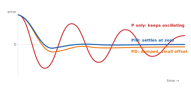
This is a proportional controller. Add derivative and integral terms and you have a full PID loop, which can also hold a target speed on each wheel regardless of battery level or load.
Troubleshooting
- Counts jump in bursts or double count: the signal is noisy or bouncing. Use the module's digital output, keep wires short, or accept only pulses that come at least a millisecond apart.
- One wheel never counts: check that the disc actually passes through the sensor slot, and that the pin is 2 or 3.
- Counts go up when reversing: single-channel optical encoders cannot sense direction. Use the motor direction you commanded, or switch to quadrature encoders.
- Slip: encoders count wheel rotation, not motion over the ground. On smooth floors, fast starts make wheels slip, so accelerate gently.
— TheSolderBench · found a mistake? tell me