Log #93 · Nov 2, 2026
Battery Charging Modules Compared: TP4056, IP5306, TP5100 and BMS Boards
Which lithium charging module should you use? A clear comparison of the TP4056, IP5306 power bank module, TP5100 1S/2S charger and 2S/3S BMS boards, with what each one actually does, its limits and the project it suits.
Search for "battery charging module" and you'll find a dozen small boards that look alike: a USB socket, a chip, a couple of LEDs and pads for a cell. They do very different jobs. Some only charge, some charge and boost to 5 V, some charge two cells in series, and some, the BMS boards, don't charge at all. Picking the wrong one is the most common reason a battery project doesn't work or, worse, slowly damages its cells. This guide compares the four modules you'll meet most often.

How lithium charging works (in 30 seconds)
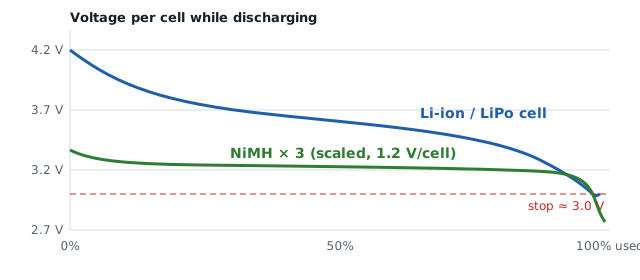
A single Li-ion or LiPo cell is charged with CC/CV: first a constant current (for example 1 A) until the cell reaches 4.2 V, then a constant voltage of 4.2 V while the current tapers off. When the current falls to about a tenth of the starting value, charging stops. Going above 4.2 V per cell or discharging below roughly 2.5–3.0 V damages the cell. Every module below handles some part of this; none handles all of it for every situation. More background is in LiPo vs Li-ion vs NiMH.
The comparison
| Module | Cells | Input | Charge current | Output | Protection |
|---|---|---|---|---|---|
| TP4056 (protected version) | 1 cell (1S) | 5 V USB (4.5–5.5 V) | up to 1 A (set by resistor) | Battery voltage, ~2.5–4.2 V | Yes, on the 6-pad version |
| IP5306 module | 1S | 5 V USB | up to about 2 A | Boosted 5 V, about 2 A | Built into the chip |
| TP5100 | 1S or 2S (jumper) | 5–18 V (more than 9 V for 2S) | up to 2 A | Battery voltage | No discharge protection |
| 2S/3S BMS | 2 or 3 in series | Needs a CC/CV charger of 8.4 V or 12.6 V | — (it doesn't charge) | Pack voltage | Over-charge, over-discharge, over-current |
TP4056: the default for one cell
The TP4056 is a linear charger for a single cell. It's cheap, simple and accurate. Buy the version with six pads (IN+, IN−, B+, B−, OUT+, OUT−): it has a second chip (DW01A) and a dual MOSFET that disconnect the load if the cell drops below about 2.5 V or if there's a short. The four-pad version only charges and offers no protection.
Limits to know:
- Input must stay below 8 V; a 9 V adapter will destroy it.
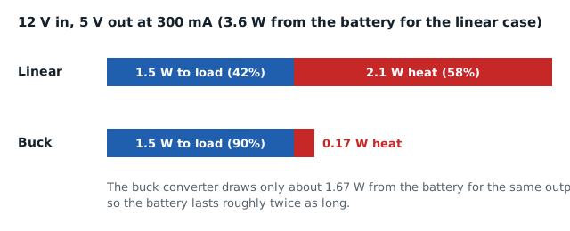
- At 1 A it gets hot, because the extra input voltage turns into heat. Lower the current (change the R3 resistor) for small cells: a 500 mAh LiPo shouldn't be charged at 1 A.
- It doesn't handle a load very well while charging: a large load can stop it from noticing that the cell is full.
It's covered in detail in how to use a TP4056, and paired with a solar panel in the solar-powered Arduino build.
IP5306: a power bank on a board
The IP5306 module is the inside of a cheap power bank. It charges one cell from USB and boosts the cell up to 5 V on a USB-A socket or pads, so you can run an Arduino, LED strip or Raspberry Pi Zero straight from it. Many versions have four LEDs that show the charge level.
Limits to know:
- It turns its output off when the load is small. If your project draws less than roughly 50 mA, the module decides nothing is connected and shuts down after about 30 seconds. A sleeping Arduino will simply lose power. The same issue affects store-bought power banks.
- Some versions need a button press to turn the output on.
- 5 V at 2 A from one cell means about 3 A from the cell. Use a good 18650 rated for it.
Great for projects that draw a steady 100 mA or more and want "charge it with a phone charger" convenience.
TP5100: one or two cells, faster
The TP5100 is a switching charger, so it runs much cooler than the TP4056 at high current. A jumper or pad selects 4.2 V (1S) or 8.4 V (2S), and it accepts a wide input range.
Limits to know:
- For 2S charging, the input must be well above 8.4 V; a 12 V adapter is the usual choice.
- It doesn't balance two cells in series. Pair it with a 2S BMS that includes balancing, or use matched cells.
- No over-discharge protection on the output.
Choose it when you need 2 A charging or a 2S (7.4 V) pack, for example for a robot whose motor driver needs more than 5 V.
BMS boards: protection, not charging
A 2S or 3S BMS (battery management system) board sits between a pack of cells in series and everything else. It watches each cell and disconnects the pack if any cell goes above about 4.25 V, below about 2.5–3.0 V, or if the current gets too high. Boards labeled "balance" or "with equalization" also bleed a little current from the fullest cell so the cells stay matched.
What it doesn't do: it doesn't regulate charging. You still need a CC/CV charger set to the pack voltage: 8.4 V for 2S and 12.6 V for 3S, with a current limit suited to your cells. Connecting a random 12 V adapter to a 3S BMS is not a charger.
Use one for any pack of two or more cells in series, wired to every cell junction (B−, B1, B2… B+) exactly as printed on the board.
Which one should you buy?
| Your project | Use |
|---|---|
| One 18650 or LiPo, low current (sensors, ESP32, Arduino Nano) | TP4056, protected version |
| One cell and you need 5 V out, project draws over 100 mA | IP5306 module |
| One cell, solar input | TP4056 with current matched to the panel, or a CN3791 MPPT module |
| 2S pack (7.4 V) for motors | TP5100 set to 2S + 2S BMS with balancing |
| 3S pack (11.1 V) | 3S BMS + a 12.6 V CC/CV charger |
Safety rules for every module
- Use protected cells or a protection board. Never rely on code alone to stop discharging.
- Don't charge below 0 °C or above about 45 °C.
- Match the charge current to the cell: a common safe rule is no more than 0.5 C (half the capacity in amps) unless the datasheet says otherwise.
- Charge on a non-flammable surface the first few times you test a new setup, and touch-check the module and cell for heat.
- Never solder directly to a cell; use a holder or buy cells with tabs.
— TheSolderBench · found a mistake? tell me