Log #45 · Oct 3, 2026
How to Use a TP4056 Lithium Battery Charger Module
Charge single Li-ion and LiPo cells safely with the TP4056 module, understand B+/B- vs OUT+/OUT-, change the charge current and avoid the common wiring mistakes.
The TP4056 module is the tiny blue board that turns a USB port into a proper lithium battery charger. It costs less than a coffee and appears in countless portable projects, from handheld game consoles to sensor nodes. Used correctly it charges a single Li-ion or LiPo cell safely. Used incorrectly it can over-discharge a battery or feed the wrong voltage to your circuit. This guide covers how it works, how to wire it and how to adjust it.
What the TP4056 does
Lithium cells need a specific charging profile, and getting it wrong shortens their life or makes them dangerous. The TP4056 chip handles it automatically:
- Constant current (CC): it pushes a fixed current (1 A by default) into the cell while the voltage rises.
- Constant voltage (CV): when the cell reaches 4.2 V, it holds that voltage while the current gradually falls.
- Termination: when the current drops to about one tenth of the set value, charging stops and the "done" LED lights.
It also includes a trickle-charge mode for deeply discharged cells (below about 2.9 V) and a thermal limit that reduces the current if the chip gets too hot.
The chip is designed for one cell with a 4.2 V full-charge voltage. It is not suitable for LiFePO₄ cells (3.6 V full), NiMH packs or two cells in series.
Two versions of the module
| Basic module | Module with protection | |
|---|---|---|
| Pads | BAT+, BAT− (sometimes IN+, IN−) | B+, B−, OUT+, OUT−, IN+, IN− |
| Extra chips | None | DW01A + FS8205A (dual MOSFET) |
| Over-discharge cutoff | No | Yes, around 2.4–2.5 V |
| Short-circuit protection | No | Yes |
| Use when | The battery has its own protection board | Bare cells, most projects |
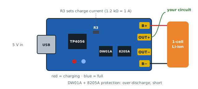
If you are unsure which you have, count the pads: six pads (including OUT+ and OUT−) means it has protection. Buy the protected version unless you have a reason not to; the price difference is negligible.
Wiring it up
For the protected module:
- B+ / B− → the battery's positive and negative terminals. Solder directly or use a holder; avoid thin, loose jumper wires.
- OUT+ / OUT− → your circuit (load).
- USB connector (or IN+ / IN− pads) → 5 V supply for charging.
Never connect the load to B+/B− on the protected version. Doing so bypasses the protection, and the battery can be drained below a safe voltage.
On the basic module, battery and load share the BAT+ and BAT− pads, so make sure the battery itself is protected (many LiPo pouches and "protected 18650" cells have a protection board built in).
Status LEDs
- Red (or one LED on): charging
- Blue or green: charge complete
- Both blinking or odd behavior: no battery connected, or a bad connection
Powering an Arduino from the battery
A lithium cell gives 3.0–4.2 V, which is neither 5 V nor a stable 3.3 V. The options are:
- 3.3 V boards (ESP32 dev boards, 3.3 V Pro Mini): use a low-dropout regulator such as the MCP1700 or HT7333 between OUT+ and the board. See voltage regulators explained.
- 5 V boards (Uno, Nano): add a small boost converter (MT3608 or a 5 V USB boost module) to raise the voltage to 5 V.
- Direct connection: some microcontrollers run fine from 3.0–4.2 V directly, but check the datasheet before relying on it.
More background on choosing a power source is in how to power an Arduino project.
Changing the charge current
The charge current is set by the resistor on the PROG pin, usually labeled R3 on the module and fitted as 1.2 kΩ for 1 A. A good rule is to charge at no more than 0.5C to 1C: for a 500 mAh LiPo, that means 250–500 mA. Charging a small cell at 1 A stresses it.
| R3 (PROG resistor) | Charge current |
|---|---|
| 10 kΩ | 130 mA |
| 5 kΩ | 250 mA |
| 3 kΩ | 400 mA |
| 2 kΩ | 580 mA |
| 1.5 kΩ | 780 mA |
| 1.2 kΩ (default) | 1000 mA |
Replacing a 0603 or 0805 surface-mount resistor is a good exercise once you are comfortable with soldering. Use tweezers and a fine tip.
Charging while the circuit runs
The TP4056 does not separate the charger from the load. If your circuit draws current while charging, the chip sees the total current and may never reach the termination point, so it never declares the cell full. For small loads (a few milliamps) this rarely matters. For larger loads, use a load-sharing circuit (a P-channel MOSFET and a Schottky diode that power the load from USB when it is plugged in) or a charger module designed for it. The alternatives (IP5306, TP5100 and BMS boards) are compared in battery charging modules compared.
Heat and safety
- At 1 A the TP4056 gets hot, often 60–80 °C. Give it some air and do not bury it in foam.
- Use a 5 V supply that can deliver at least the set charge current plus a margin.
- Never connect a cell backwards. Most modules have no reverse-polarity protection, and the chip will be destroyed instantly.
- Do not charge swollen, punctured or very old cells. Read more about cell types and safety in LiPo vs Li-ion vs NiMH.
Troubleshooting
- LEDs flicker without a battery: normal. The chip searches for a cell.
- Never shows "done": the load is drawing current during charging, or the cell is damaged.
- No output on OUT+ after the battery ran flat: the protection has tripped. Plug in USB for a few seconds to reset it.
- Battery voltage stops at 4.1 V: some cheap modules use clone chips with lower accuracy. That is safe, just slightly less capacity.
— TheSolderBench · found a mistake? tell me