Log #25 · Sep 27, 2026
Relay Modules: Switching Big Loads Safely
How relay modules let an Arduino switch lamps, pumps and fans, what COM, NO and NC mean, active-low inputs, and the safety rules for higher voltages.
A relay is a switch operated by electricity. A small current through its coil pulls a metal contact across, and that contact can switch a completely separate circuit, even one at a much higher voltage. Relay modules let an Arduino turn on lamps, pumps, fans and heaters that it could never power directly. They are also one of the few hobby parts that can connect to mains voltage, so it pays to understand them properly.
Inside a relay module
A typical single-channel module carries:
- A relay such as the SRD-05VDC-SL-C, with a 5 V coil and contacts rated around 10 A at 250 V AC or 30 V DC
- A transistor that drives the coil, since the coil needs about 70 mA, more than a pin should supply
- A flyback diode across the coil to absorb the switch-off spike, as explained in the diodes guide
- A status LED
- On many boards, an optocoupler that separates the input signal from the coil circuit
The three output terminals
The screw terminal has three connections:
| Terminal | Meaning | Behavior |
|---|---|---|
| COM | Common | The moving contact |
| NO | Normally open | Connected to COM only when the relay is on |
| NC | Normally closed | Connected to COM when the relay is off |
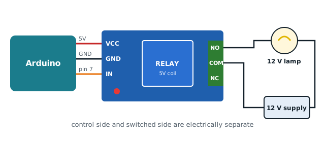
For most uses, wire the load through COM and NO: the load is off until the Arduino activates the relay, and it stays off if the Arduino loses power. Use NC only when the load must stay on by default.
Wiring the control side
| Module pin | Arduino |
|---|---|
| VCC | 5 V |
| GND | GND |
| IN | Pin 7 |
Active-low inputs
Many relay modules are active low: the relay turns on when IN is pulled LOW and off when it is HIGH. It feels backwards, and it means the relay can click on briefly while the Arduino boots, when pins float. Two good habits:
const int RELAY = 7;
const bool RELAY_ON = LOW;     // change to HIGH for active-high modules

void setup() {
  digitalWrite(RELAY, !RELAY_ON);   // set the "off" level first...
  pinMode(RELAY, OUTPUT);           // ...then make it an output
}

void setRelay(bool on) { digitalWrite(RELAY, on ? RELAY_ON : !RELAY_ON); }
Writing the pin level before calling pinMode avoids a glitch at startup. Test your module once to see which level switches it on, and set RELAY_ON accordingly.
The JD-VCC jumper
Boards with an optocoupler often have a jumper joining VCC and JD-VCC. With the jumper fitted, the coil runs from the same 5 V as the logic. Removing it and feeding JD-VCC from a separate 5 V supply fully isolates the coil current from the Arduino, which helps when switching several relays. For one or two relays, leave the jumper on.
What relays are good at, and what they are not
Good for: - On/off switching of AC or DC loads: lamps, pumps, fans, heaters within the contact rating - Complete electrical isolation between the Arduino and the load - Loads that switch rarely, a few times per minute at most
Not good for: - PWM or speed control. A relay clicks mechanically and wears out; its contacts are rated for something like 100 000 operations. Use a transistor or MOSFET for speed control. - Very small signals. Mechanical contacts are not reliable for tiny currents. - Large motors or inductive loads near the rating. Their startup current can weld contacts. Choose a relay with plenty of margin.
For silent, fast switching of AC loads, solid-state relays (SSRs) exist, but most only work with AC and leak a small current when off.
Safety with mains voltage
Mains electricity can kill. The relay isolates your Arduino, but the wiring on the output side carries full mains voltage.
- If you are not confident with mains wiring, do not do it. Switch a low-voltage load instead: a 12 V LED strip, a 12 V pump or a USB fan are just as good for learning.
- Never work on a circuit while it is plugged in.
- Keep all mains wiring inside a closed, non-conductive enclosure, with cable strain relief.
- Keep low-voltage and mains wiring physically separate, with clear spacing.
- Cheap relay modules often have mains traces very close to low-voltage parts. Treat the whole board as live when connected.
- Respect the contact rating, and fuse the load circuit.
- Follow your local electrical regulations.
Project ideas
- Dusk light: combine the relay with the LDR circuit from the light sensor guide to switch a 12 V lamp at night.
- Timed pump: switch a 12 V pump for a set time using the millis() pattern.
- Fan thermostat: switch a fan when a DS18B20 reads above a set temperature, with a couple of degrees of hysteresis so it does not chatter.
Troubleshooting
- LED lights but no click: the coil is not getting enough current. Check that VCC really is 5 V and that JD-VCC is powered.
- Relay on at startup: active-low module; set the pin HIGH before
pinMode. - Arduino resets when the relay switches: power the coils separately via JD-VCC, and add a capacitor across the supply, as covered in choosing capacitors.
— TheSolderBench · found a mistake? tell me