Log #34 · Sep 27, 2026
Breadboard Basics and Common Mistakes
How the rows and rails inside a solderless breadboard connect, how to lay out circuits cleanly, and the mistakes that cause most beginner failures.
A solderless breadboard lets you build and change circuits in minutes, without a soldering iron. It is also where most "my circuit doesn't work" problems start, because the connections hidden inside it are easy to misunderstand. Spend ten minutes learning how it is wired and you will avoid hours of confusion.
What is inside
Under the plastic, a breadboard has rows of metal spring clips. Each clip grabs any wire or leg pushed into its holes and connects them together.
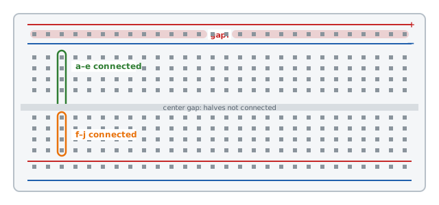
The terminal strips
The main area is made of short rows, usually labeled 1 to 30 or 1 to 63, with columns lettered a–e and f–j.
- The five holes a, b, c, d, e in one row are connected.
- The five holes f, g, h, i, j in the same row are connected to each other.
- The two halves are not connected across the center gap.
The gap exists for chips. A DIP chip straddles the gap so each of its pins lands in its own row, with four free holes left for connections.
The power rails
The long strips along the edges, usually marked with a red + and a blue − line, run the length of the board. They distribute power and ground so you can reach them from anywhere.
Two important details:
- The rails on the left and right sides are separate. Connect them with jumper wires if you want power on both sides.
- On many full-size boards, each rail is split in the middle. The red and blue lines often have a visible gap halfway along. If they do, bridge the two halves with a short jumper, or the bottom half of your circuit has no power.
Building cleanly
A tidy layout is not about looks. It makes wiring mistakes easy to spot.
- Use color consistently: red for positive supply, black for ground, other colors for signals.
- Keep wires short and flat against the board. A tangle of long loops hides errors and picks up noise.
- Build in stages: power first, then one part at a time, testing as you go.
- Follow the schematic direction: place parts roughly where they appear on the diagram, left to right.
- Trim LED and resistor legs for permanent breadboard builds so they cannot touch each other.
The most common mistakes
1. Parts plugged into the same row
A resistor inserted with both legs in the same row is short-circuited: both ends connect to the same clip, so current bypasses it. Every component must bridge between rows. The same goes for a button: its legs must sit in different rows, usually across the center gap.
2. The rail gap
Everything at the top works, nothing at the bottom does. Check for split power rails.
3. LED backwards
LEDs only conduct one way. The longer leg, the anode, goes toward positive. If an LED stays dark, flip it before anything else. See your first Arduino sketch for the full LED wiring.
4. No common ground
When a separate battery powers motors or a module, its ground must connect to the Arduino's GND. Without it, signals have no shared reference and behave randomly.
5. Loose or worn contacts
Cheap or old breadboards have tired clips, and thin component legs may not grip. Wiggle a suspicious wire; if the circuit flickers, move it to another row. Thick leads, like some power connectors, can permanently stretch a clip.
6. Off-by-one rows
Counting holes by eye in dim light is error-prone. Use the printed row numbers, and double-check before powering up.
How to debug a breadboard circuit
- Unplug power and compare each wire to the diagram, one at a time.
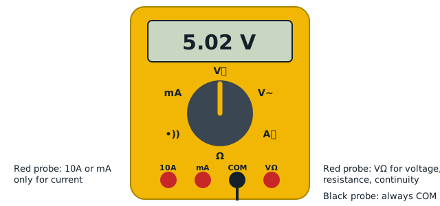
- Check power first: with the circuit on, measure between the + and − rails with a multimeter. It should read your supply voltage at both ends of the board.
- Follow the signal: measure the voltage at each point along the path, from the Arduino pin to the load.
- Use continuity mode with the power off to confirm that two points really connect, as explained in how to use a multimeter.
- Swap suspect jumper wires. Broken wires inside the insulation are surprisingly common.
Limits of breadboards
Breadboards are great for low-voltage, low-current prototypes, but they have limits:
- Current: the thin clips handle roughly 1 A at most. Motor currents should run through proper wiring, not across the board.
- Speed: the long parallel strips add capacitance that disturbs very fast signals, like those in radio circuits.
- Mains voltage: never. Breadboards are only for low voltages.
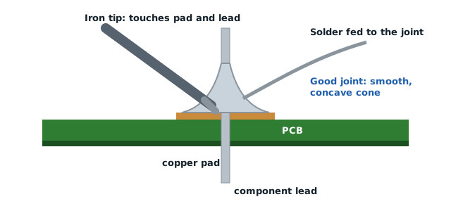
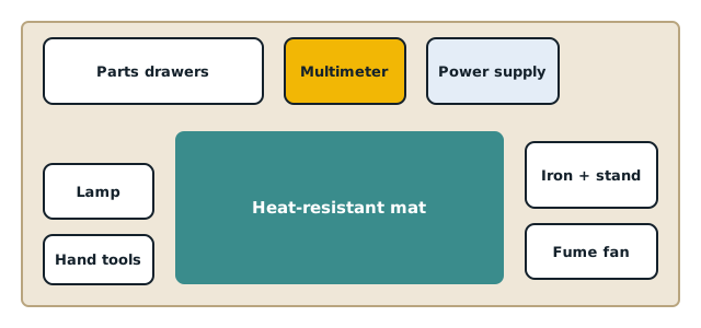
When a design works and you want it to last, move it to perfboard and solder it, following how to solder. Keep a couple of breadboards in your kit; our bench tools list recommends one full-size and one half-size board to start.
— TheSolderBench · found a mistake? tell me