Log #32 · Sep 27, 2026
How to Use a Multimeter
Measure voltage, current, resistance and continuity safely, set the right mode and range, and avoid the mistake that blows the meter's fuse.
A multimeter is the most important tool on an electronics bench after the soldering iron. It answers the questions that stop most projects: Is the battery charged? Is this wire connected? Which resistor is this? How much current is my robot drawing? This guide shows how to make each measurement, in plain steps, with the safety rules that protect you and the meter.
The parts of a multimeter
- Display: shows the reading and units.
- Rotary dial: selects what to measure, such as V, A, Ω or continuity.
- Probes: red and black leads with metal tips.
- Jacks: usually three or four sockets.
- COM: common. The black probe always goes here.
- VΩ (often with mA): the red probe goes here for voltage, resistance, continuity and small currents on many meters.
- A or 10A: the red probe goes here only for measuring large currents.
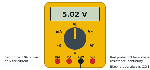
Autoranging meters pick the scale automatically. Manual ranging meters make you choose, such as 20 V; always choose a range higher than what you expect.
Measuring DC voltage
Voltage is measured across something, with the circuit powered.
- Black probe in COM, red in VΩ.
- Turn the dial to V⎓ (DC volts, the V with a straight line).
- Touch black to ground (or the negative side) and red to the point you want to measure.
Example: check a 9 V battery. A fresh one reads about 9.5 V; below about 7 V it is nearly flat. On an Arduino, black on GND and red on the 5V pin should read close to 5 V.
If the reading is negative, the probes are swapped. Nothing is damaged; the meter is just telling you the polarity. If voltage concepts are still fuzzy, start with voltage, current and resistance.
Measuring resistance
Resistance is measured with the circuit unpowered. The meter sends its own small current, and outside voltage gives wrong readings or can damage it.
- Red probe in VΩ, dial on Ω.
- Touch the probes to each end of the resistor. Polarity does not matter.
- Read the value, noting the unit: Ω, kΩ or MΩ.
For accurate results, measure a resistor out of the circuit. Other parts connected in parallel change the reading. Your fingers on both leads also add a parallel path through your body at high values.
Continuity: the beep test
Continuity mode, marked with a sound-wave or diode symbol, beeps when there is a low-resistance path between the probes. With the circuit unpowered:
- Check a wire or cable end to end.
- Find which pins of a switch connect when pressed.
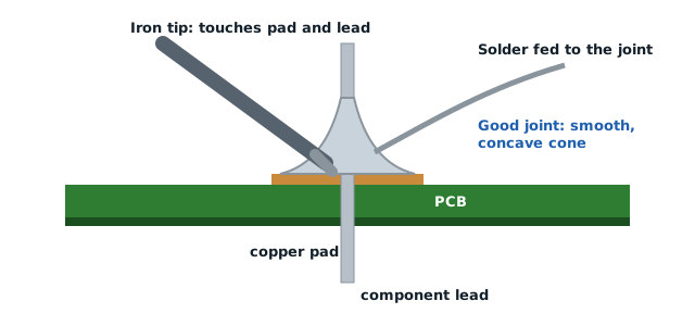
- Check a soldered joint for a good connection, or two neighboring joints for an accidental bridge. See how to solder for fixing bridges.
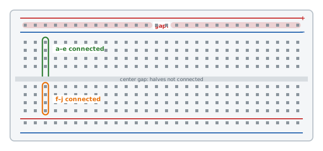
It is the quickest way to find a broken jumper wire, which is the cause of more "mystery" breadboard failures than anything else.
Measuring current
Current is measured in series: the current must flow through the meter. This is the measurement where most beginners blow the meter's fuse.
- Turn off the circuit.
- Move the red probe to the mA jack for small currents, or 10A for large ones. If unsure, start with 10A.
- Set the dial to A⎓ or mA⎓.
- Break the circuit at one point and connect the meter across the gap, so the current has to pass through it.
- Turn the power on and read.
Example: to measure how much your robot draws, disconnect the battery's red wire, then connect red probe to the battery + and black probe to the wire you removed.
The fuse-blowing mistake
In current mode, the meter is nearly a short circuit. If you leave the red probe in the current jack and then touch the probes across a battery as if measuring voltage, a large current flows straight through the meter and blows its internal fuse, or worse. Always move the red probe back to VΩ as soon as you finish measuring current.
Other useful modes
- Diode test: shows the forward voltage of a diode or LED, and often lights up an LED faintly. Handy to identify an LED's color and polarity.
- AC volts (V~): for mains or transformer outputs. Only measure mains if you know what you are doing and your meter is rated for it (CAT II or higher).
- Capacitance and frequency on some meters.
Choosing a first multimeter
A basic autoranging meter with continuity beep, a 10 A current range and a fused current input covers almost all hobby work. Features worth paying a little more for: a fast continuity beep, a backlit display and probes with sharp tips. For mains work, buy a meter with a proper safety category rating from a known brand.
Practice exercise
Grab a battery pack, a few resistors and an LED. Measure the pack voltage, read the resistor values and compare them to their color codes, then build an LED circuit and measure its current in series. You will have used every core mode in ten minutes, and you will be ready to debug power problems like those in how to power an Arduino project.
— TheSolderBench · found a mistake? tell me