Log #01 · Sep 27, 2026
What Are Voltage, Current and Resistance?
The three quantities behind every circuit, explained with a water-tank model, real numbers and the mistakes beginners make most often.
Every circuit you will ever build, from a blinking LED to a six-legged robot, comes down to three quantities: voltage, current and resistance. If you understand how they relate, datasheets stop looking like a foreign language and most "why did my LED burn out?" moments disappear. This guide explains each one with a physical picture, gives you the units you will see on real parts, and ends with the habits that keep your components alive.
The water-tank picture
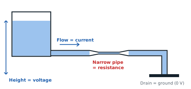
The classic way to picture a circuit is a water system. It is not perfect, but it gets you surprisingly far.
- Voltage is the pressure difference between two points, like the height difference between a full tank and a drain.
- Current is how much water actually flows past a point each second.
- Resistance is how narrow the pipe is. A narrow pipe lets less water through for the same pressure.
Raise the tank higher and more water flows. Squeeze the pipe and less flows. That single sentence is Ohm's law in plain words, and we will turn it into numbers in the Ohm's law guide.
Voltage: the push
Voltage is measured in volts (V). It is always measured between two points, which is why a multimeter has two probes. When someone says "this pin is at 5 V", they mean 5 V relative to ground, the reference point of the circuit.
Common voltages on a hobby bench:
| Source | Typical voltage |
|---|---|
| AA alkaline cell | 1.5 V (drops to about 1.1 V when nearly empty) |
| Li-ion or LiPo cell | 3.7 V nominal, 4.2 V fully charged |
| USB port | 5 V |
| Arduino Uno logic | 5 V |
| ESP32 and Raspberry Pi logic | 3.3 V |
| 9 V battery | 9 V |
A higher voltage does not mean a part will "use" more. It means the source can push harder, and whether that push causes damage depends on what limits the current.
Current: the flow
Current is measured in amperes (A), usually shortened to amps. On small electronics you will mostly see milliamps (mA): 1 A equals 1000 mA.
Some useful reference points:
- A standard 5 mm LED is happy at 10 to 20 mA.
- An Arduino Uno pin should stay under about 20 mA for continuous use, with 40 mA as the absolute maximum.
- A small hobby servo can pull 500 mA or more when it starts moving.
- A USB 2.0 port is designed to supply 500 mA.
The key idea: current is drawn, voltage is supplied. A 5 V, 2 A phone charger does not force 2 A into your circuit. It can deliver up to 2 A if the circuit asks for it. That is why connecting a small sensor to a large power supply is fine, as long as the voltage matches.
Resistance: the limit
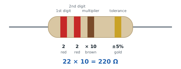
Resistance is measured in ohms (Ω). Resistors come in values like 220 Ω, 1 kΩ (1000 Ω) and 10 kΩ. You can read the value from the colored bands on the body, as explained in our resistor color code guide.
Everything has some resistance. Copper wire has very little, which is why a wire straight from + to − of a battery (a short circuit) lets a huge current flow and heats up fast. A resistor adds a known, controlled amount so the current stays where you want it.
Power: where the heat comes from
A fourth quantity ties the other three together: power, measured in watts (W).
Power = Voltage × Current
A resistor dropping 7 V while 21 mA flows through it turns 7 × 0.021 ≈ 0.15 W into heat. A standard through-hole resistor is rated for 0.25 W, so it is fine. If the result had been 0.5 W, you would need a bigger resistor or it would get hot enough to discolor and eventually fail.
Putting it together: an LED example
Say you want to light a red LED from a 9 V battery. The LED drops about 2 V and wants around 20 mA.
- Voltage left for the resistor: 9 V − 2 V = 7 V.
- Resistance needed: 7 V ÷ 0.020 A = 350 Ω. The nearest common value above that is 390 Ω; 330 Ω also works and gives about 21 mA.
- Power in the resistor: 7 V × 0.021 A ≈ 0.15 W, safe for a 0.25 W part.
Skip the resistor and nothing limits the current, so the LED fails within seconds. This is the single most common beginner mistake.
Measuring all three
You can check each quantity with a multimeter:
- Voltage: probes across the part, meter in V mode, circuit powered.
- Current: meter placed in series, so the current flows through it, probes in the mA or A jack.
- Resistance: circuit unpowered, probes across the part.
Our multimeter guide walks through each measurement step by step, including the mistake that blows the meter's internal fuse.
Habits that keep parts alive
- Check the voltage a part expects before connecting it. A 3.3 V sensor on a 5 V line may not survive.
- Always add a current-limiting resistor to LEDs.
- Estimate current before powering motors from a microcontroller pin. Motors need a driver board.
- Calculate power for any resistor dropping more than a few volts.
Once these three quantities feel natural, move on to Ohm's law with real examples, where you will size resistors for LEDs, sensors and voltage dividers.
— TheSolderBench · found a mistake? tell me