Log #99 · Nov 9, 2026
JSN-SR04T Waterproof Ultrasonic Sensor with Arduino
How the JSN-SR04T waterproof ultrasonic sensor differs from the HC-SR04, its 25 cm blind zone and wide beam, wiring, reliable Arduino code with filtering, and tips for tanks, cars and outdoor projects.
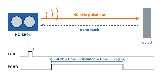
The HC-SR04 is perfect on a desk, but humidity, rain and splashes slowly kill it. The JSN-SR04T solves that: the ultrasonic transducer is a sealed, car-parking-sensor style probe on a long cable, and the electronics sit on a separate board you can keep dry. It measures distance the same way and uses almost the same code, with two differences you must design around: a large blind zone and a wider beam.

JSN-SR04T vs HC-SR04
| HC-SR04 | JSN-SR04T | |
|---|---|---|
| Transducers | Two open cans (send + receive) | One sealed probe that does both |
| Waterproof | No | Probe yes, board no |
| Minimum distance | ~2–3 cm | ~20–25 cm |
| Maximum distance | ~4 m | ~4.5–6 m |
| Beam | Narrow (~15°) | Wider |
| Cable | — | ~2.5 m between probe and board |
| Supply | 5 V | 5 V (v3 boards also run from 3.3 V) |
| Interface | Trigger/echo | Trigger/echo (some versions add serial modes) |
Why the blind zone exists
The HC-SR04 has a separate receiver, so it can listen while the transmitter is still ringing. The JSN-SR04T uses one transducer to both send and receive. After it fires, the probe keeps vibrating for a short time, and it can't hear an echo until it settles. Any echo that comes back during that time is lost. In practice, readings below about 20–25 cm are missing or wrong.
Design rule: mount the probe so the closest thing you want to measure is at least 25 cm away. For a water tank, that means 25 cm between the probe and the full level.
Wiring
The control board has four pins:
| JSN-SR04T board | Arduino |
|---|---|
| 5V | 5V |
| Trig (or Rx) | D9 |
| Echo (or Tx) | D10 |
| GND | GND |
Plug the probe's cable into the connector on the board. If you need to extend it, extend the four-wire side (board to Arduino) rather than the probe cable, which is matched to the board.
The board itself isn't waterproof. Put it in a small sealed box, with the probe cable passing through a cable gland or a hole sealed with silicone.
The code
The JSN-SR04T works with HC-SR04 code, with two adjustments: a longer trigger pulse (some board versions ignore 10 µs, 20 µs works on all of them) and a longer pause between readings, since the probe needs time to settle.
const int TRIG = 9;
const int ECHO = 10;
const int MIN_CM = 25;           // blind zone
const int MAX_CM = 450;

long readCm() {
  digitalWrite(TRIG, LOW);
  delayMicroseconds(5);
  digitalWrite(TRIG, HIGH);
  delayMicroseconds(20);         // 20 µs works on every board version
  digitalWrite(TRIG, LOW);
  unsigned long us = pulseIn(ECHO, HIGH, 30000UL);  // ~5 m timeout
  if (us == 0) return -1;        // no echo
  long cm = us / 58;
  if (cm < MIN_CM || cm > MAX_CM) return -1;        // outside the valid range
  return cm;
}

long medianCm() {
  long r[5];
  int n = 0;
  for (int i = 0; i < 5; i++) {
    long d = readCm();
    if (d > 0) r[n++] = d;
    delay(70);                   // let the probe settle between pings
  }
  if (n == 0) return -1;
  for (int i = 1; i < n; i++) {  // sort the valid readings
    long k = r[i];
    int j = i - 1;
    while (j >= 0 && r[j] > k) { r[j + 1] = r[j]; j--; }
    r[j + 1] = k;
  }
  return r[n / 2];               // the middle one
}

void setup() {
  pinMode(TRIG, OUTPUT);
  pinMode(ECHO, INPUT);
  Serial.begin(9600);
}

void loop() {
  long d = medianCm();
  if (d < 0) Serial.println("out of range");
  else {
    Serial.print(d);
    Serial.println(" cm");
  }
  delay(200);
}
What the code does:
- Readings inside the blind zone or beyond the useful range are rejected instead of being reported as real distances.
- The median of five readings removes the occasional wild value, which the wide beam makes more common than on the HC-SR04.
- 70 ms between pings lets each echo die out before the next one starts.
About the board versions and modes
You'll find v2.0 and v3.0 boards, and look-alikes such as the AJ-SR04M. Many have a resistor position (often marked R27 on v2 or R19 on v3) that selects a mode: the default trigger/echo mode used above, or modes that measure continuously and send the distance over serial. The resistor values for each mode differ between versions, so check the documentation for your exact board before changing anything. For most projects, the default mode is the simplest and most reliable.
Where it works well
- Water tanks and wells: a probe above the water, the board in a dry box. This is the permanent version of the water tank level monitor, with the full mark at least 25 cm below the probe.
- Car or garage parking sensors: the probe is the same style as a car's bumper sensor. Combine it with the display logic from the parking sensor project, keeping in mind that the car must stop farther than 25 cm away.
- Outdoor robots and lawn projects: rain and dust don't bother the probe.
- Snow depth or river level stations, pointing down from a fixed post.
Getting stable readings
- Point it at large, flat, hard surfaces. Water, walls and car bumpers reflect well; grass, foam and fabric absorb sound.
- Keep the beam clear. Because the cone is wide, a pipe, a tank wall or a post within the beam can return an echo first. Give it more clearance than you would an HC-SR04.
- Mount it rigidly. A probe that vibrates or swings on its cable gives noisy readings.
- Account for temperature outdoors. The speed of sound changes by about 0.6 m/s per °C. For accurate long distances, measure the air temperature and use 331.3 + 0.606 × °C m/s instead of the fixed 58 µs/cm.
Troubleshooting
- Always "out of range": check that TRIG and ECHO aren't swapped, that the board has 5 V, and that the target is farther than 25 cm.
- Readings around 20–30 cm that never change: the probe is hearing its own ringing, or something sits inside the blind zone. Move the target farther away.
- Random short readings: an object, wall or pipe inside the wide beam. Reposition the probe or aim it slightly away.
- Stopped working after weeks outdoors: water reached the board or the connector. Seal the box and the cable entry.
— TheSolderBench · found a mistake? tell me