Log #14 · Sep 27, 2026
Reading a Potentiometer and a Joystick with Arduino
How potentiometers and analog thumb joysticks work, how to wire and read them, and how to add a dead zone and smoothing for steady control.
A potentiometer is the simplest analog input you can connect to an Arduino, and a thumb joystick is just two potentiometers and a button in one package. Together they cover volume knobs, menu selectors, robot remote controls and camera pan-and-tilt rigs. This guide explains how both work and how to read them reliably.
How a potentiometer works
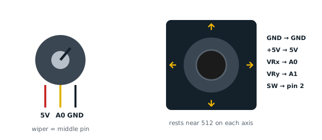
A potentiometer, or pot, is a resistor with a third terminal called the wiper that slides along it.
- The two outer pins connect to the ends of the resistive track.
- The middle pin is the wiper.
Connect the outer pins to 5 V and GND, and the wiper outputs a voltage anywhere between 0 and 5 V depending on the knob position. It is a voltage divider whose ratio you set by hand, as explained in the Ohm's law guide.
The total resistance, often 10 kΩ, does not change the reading, only how much current the pot draws: 5 V ÷ 10 kΩ = 0.5 mA. Values from 1 kΩ to 100 kΩ all work; 10 kΩ is the usual choice.
Linear and logarithmic pots
Pots marked B (for example B10K) are linear: turning halfway gives half the voltage. Pots marked A are logarithmic, made for audio volume. For Arduino inputs, use linear B pots, or your readings will change slowly at one end and quickly at the other.
Reading a potentiometer
void setup() { Serial.begin(9600); }

void loop() {
  int raw = analogRead(A0);                 // 0 to 1023
  int percent = map(raw, 0, 1023, 0, 100);  // 0 to 100 %
  Serial.print("knob: ");
  Serial.print(percent);
  Serial.println(" %");
  delay(100);
}
The analog pins guide explains the 0 to 1023 range. Use map() to convert it into whatever you need: an angle for a servo, a PWM value from 0 to 255 for LED brightness or motor speed, or a menu index.
How a thumb joystick works
A common joystick module, like those in starter kits, has five pins:
| Pin | Meaning | Connect to |
|---|---|---|
| GND | Ground | GND |
| +5V | Supply | 5 V |
| VRx | X-axis potentiometer | A0 |
| VRy | Y-axis potentiometer | A1 |
| SW | Push button (press the stick) | Pin 2 |
Inside, one pot moves with left–right motion and another with up–down motion. Springs return the stick to the middle, so at rest each axis reads roughly 512, the midpoint of the 0 to 1023 range.
Reading a joystick
const int X = A0, Y = A1, SW = 2;

void setup() {
  pinMode(SW, INPUT_PULLUP);    // the button pulls the pin LOW when pressed
  Serial.begin(9600);
}

void loop() {
  int x = analogRead(X);
  int y = analogRead(Y);
  bool pressed = digitalRead(SW) == LOW;
  Serial.print("x:"); Serial.print(x);
  Serial.print(" y:"); Serial.print(y);
  Serial.print(" button:"); Serial.println(pressed);
  delay(100);
}
Open the Serial Monitor and move the stick. Depending on how the module is mounted, "up" may read high or low; flip the direction in code if needed.
Adding a dead zone
In practice, the resting value is rarely exactly 512. It may sit at 498 on one module and 530 on another, and it jitters by a few counts. If you use the raw value to drive motors, the robot creeps slowly even when you are not touching the stick.
The fix is a dead zone: treat everything close to center as exactly zero.
int centerX = 512;   // measured at startup, see below
const int DEAD = 40;

int axis(int raw, int center) {
  int v = raw - center;                    // about -512 .. +512
  if (abs(v) < DEAD) return 0;             // inside the dead zone
  return constrain(map(v, -512, 512, -255, 255), -255, 255);
}

void setup() {
  centerX = analogRead(A0);                // read the resting position
}
Measuring the center in setup(), while nobody touches the stick, makes each module calibrate itself.
Smoothing noisy readings
Analog readings wobble by a few counts because of electrical noise. Two simple filters:
- Average several readings: add up 8 reads and divide by 8.
- Exponential smoothing, which uses almost no memory:
float smooth = 0;
void loop() {
  int raw = analogRead(A0);
  smooth = smooth * 0.8 + raw * 0.2;       // higher first number = smoother, slower
}
Also keep the pot's wires short and away from motor wires, and add a 100 nF capacitor between the wiper and GND if the noise persists.
Project idea: joystick-driven robot
Map the Y axis to forward speed and the X axis to turning, then mix them:
left motor = speed + turn, right motor = speed − turn
Feed those values into the motor functions from the obstacle-avoiding robot, and you have a wired remote-control car. Replace the wire with a pair of radio modules later, and it becomes wireless.
— TheSolderBench · found a mistake? tell me