Log #08 · Sep 27, 2026
Digital vs Analog Pins on Arduino
How digital inputs read buttons, how analog inputs turn voltages into numbers from 0 to 1023, and what PWM outputs really do.
An Arduino talks to the world through its pins. Some pins only understand on and off, some can measure a range of voltages, and some can fake an in-between output by switching very fast. Knowing which is which is the difference between a sensor that works and one that returns nonsense. This guide covers the three pin behaviors you will use constantly, with code for each.
Digital pins: on or off
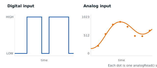
A digital pin has two states: HIGH (close to 5 V on an Uno) or LOW (close to 0 V). On the Uno these are pins 0 to 13. You already used one as an output in the blink sketch.
Reading a button
To read a digital input, set the pin to INPUT_PULLUP. This connects an internal resistor of roughly 20 to 50 kΩ from the pin to 5 V, so the pin reads HIGH when nothing is connected. Wire a push button between the pin and GND: pressing it pulls the pin LOW.
const int BUTTON = 2;
const int LED = 13;

void setup() {
  pinMode(BUTTON, INPUT_PULLUP);
  pinMode(LED, OUTPUT);
}

void loop() {
  bool pressed = digitalRead(BUTTON) == LOW;  // LOW means pressed
  digitalWrite(LED, pressed ? HIGH : LOW);
}
Why the pull-up matters
Without a pull-up or pull-down resistor, an unconnected input is floating. It picks up electrical noise from your hand, nearby wires or the air, and randomly flips between HIGH and LOW. If your button "presses itself", a missing pull-up is the usual cause.
Pins 0 and 1
Pins 0 (RX) and 1 (TX) are shared with the USB serial connection. Leave them free while you are learning, or uploads may fail.
Analog inputs: measuring a voltage
Pins A0 to A5 on the Uno contain an analog-to-digital converter (ADC). It measures the voltage on the pin and returns a whole number:
- 0 V reads as 0
- 5 V reads as 1023
- Everything in between scales linearly
That is a 10-bit converter, 2¹⁰ = 1024 steps, so each step is about 5 ÷ 1024 ≈ 4.9 mV.
Reading a potentiometer
A potentiometer is a knob with three legs. Connect the outer legs to 5 V and GND and the middle leg to A0. Turning the knob moves the middle voltage from 0 to 5 V.
void setup() {
  Serial.begin(9600);
}

void loop() {
  int raw = analogRead(A0);            // 0 to 1023
  float volts = raw * 5.0 / 1023.0;    // convert to volts
  Serial.print(raw);
  Serial.print("  ->  ");
  Serial.print(volts, 2);
  Serial.println(" V");
  delay(200);
}
Open Tools → Serial Monitor at 9600 baud and turn the knob to watch the numbers change. The same conversion works for analog sensors like the LM35 in our temperature sensor comparison.
Measuring more than 5 V
Never connect more than 5 V directly to an analog pin on an Uno, or more than 3.3 V on an ESP32. To measure a 9 V battery, scale it down first with a voltage divider, as shown in the Ohm's law examples.
PWM outputs: faking analog
The Uno cannot output a true in-between voltage. Instead, pins marked with a ~ (3, 5, 6, 9, 10 and 11) can use pulse-width modulation (PWM): they switch on and off hundreds of times per second, and the fraction of time spent on, the duty cycle, sets the average power.
analogWrite(pin, value) takes a value from 0 to 255:
| Value | Duty cycle | Effect on an LED |
|---|---|---|
| 0 | 0% | Off |
| 64 | 25% | Dim |
| 128 | 50% | Medium |
| 255 | 100% | Full brightness |
const int LED = 9;   // must be a ~ pin

void setup() {
  pinMode(LED, OUTPUT);
}

void loop() {
  for (int v = 0; v <= 255; v++) { analogWrite(LED, v); delay(4); }
  for (int v = 255; v >= 0; v--) { analogWrite(LED, v); delay(4); }
}
The LED fades up and down smoothly because your eye averages the fast flicker. PWM is also how motor drivers control speed, which you will use in the motor driver guide.
Can analog pins be digital?
Yes. On the Uno, A0 to A5 also work as digital pins 14 to 19, so you can use pinMode(A2, OUTPUT) and digitalWrite(A2, HIGH) when you run out of digital pins. The reverse is not true: pins 0 to 13 cannot measure voltages.
Quick summary
- digitalRead / digitalWrite: on or off, any digital pin, plus A0–A5.
- analogRead: 0–1023, only on A0–A5 (on an Uno).
- analogWrite: 0–255 PWM, only on ~ pins.
- Use
INPUT_PULLUPfor buttons to avoid floating inputs.
With inputs and outputs covered, you are ready for real sensors. Start with the HC-SR04 ultrasonic distance sensor, which uses two digital pins to measure distance.
— TheSolderBench · found a mistake? tell me