Log #76 · Oct 19, 2026
Control 16 Servos with a PCA9685 Driver and Arduino
Drive up to 16 servos from two Arduino pins with the PCA9685 I2C board. Wiring logic and servo power correctly, the Adafruit library, angle and microsecond code, calibration, and chaining boards.
An Arduino Uno can drive a handful of servos with the Servo library, but each one needs a pin, the timing gets shaky when other libraries run, and powering them is a headache. The PCA9685 board solves all three: it generates 16 independent servo signals in hardware, talks to the Arduino over I²C with just two wires, and has a separate power input for the servos. It's the standard choice for robot arms, hexapods and animatronics.
What the board does
The PCA9685 is a 16-channel, 12-bit PWM chip. You tell it once "make a 50 Hz signal on channel 3 with a 1.5 ms pulse" and it keeps generating that signal on its own, perfectly steady, while your Arduino does other things. It doesn't use any Arduino timers, so it can't conflict with other libraries, one of the jitter causes listed in why is my servo jittering.
Wiring
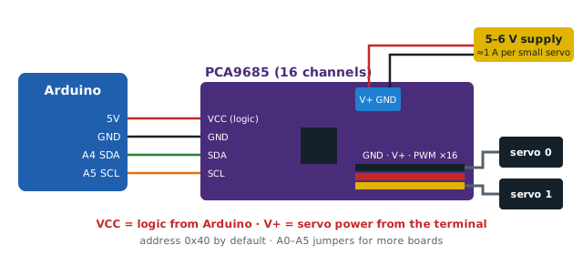
Logic side (left header):
| PCA9685 | Arduino Uno / Nano |
|---|---|
| GND | GND |
| OE | not connected (or GND); pulled low = outputs on |
| SCL | A5 |
| SDA | A4 |
| VCC | 5 V (logic only) |
| V+ | leave unconnected here |
Servo power (blue screw terminal): a 5–6 V supply that can handle the servos' current: roughly 1 A per small servo (SG90) and 2–3 A per big one (MG996R) if they move together. A 5 V 4 A adapter or a 6 V battery pack works for a few small servos.
Servos: plug them into the 3-pin headers, matching the colors: black/brown = GND, red = V+, yellow/orange = signal (PWM).
The two most important rules: 1. VCC is logic power, V+ is servo power. Never connect 6 V or more to VCC. 2. Don't power servos from the Arduino's 5 V pin. Use the screw terminal.
If the board has an empty spot for a big capacitor near the terminal, solder in a 470–1000 µF electrolytic (watch the polarity). It helps when many servos start at once.
Install the library
In the Library Manager, install Adafruit PWM Servo Driver Library.
The code
#include <Wire.h>
#include <Adafruit_PWMServoDriver.h>

Adafruit_PWMServoDriver pwm = Adafruit_PWMServoDriver(0x40);

// Pulse range for your servos; find the real values (see calibration below)
const int US_MIN = 600;    // microseconds at 0 degrees
const int US_MAX = 2400;   // microseconds at 180 degrees

void setAngle(uint8_t channel, int angle) {
  angle = constrain(angle, 0, 180);
  int us = map(angle, 0, 180, US_MIN, US_MAX);
  pwm.writeMicroseconds(channel, us);
}

void setup() {
  Serial.begin(9600);
  pwm.begin();
  pwm.setOscillatorFrequency(27000000);   // nominal 25 MHz; 27 MHz matches many boards in practice
  pwm.setPWMFreq(50);                     // standard servo frequency
  delay(10);

  for (uint8_t ch = 0; ch < 4; ch++) setAngle(ch, 90);   // center four servos
}

void loop() {
  // Sweep servo 0 slowly while the others hold their position
  for (int a = 30; a <= 150; a++) { setAngle(0, a); delay(15); }
  for (int a = 150; a >= 30; a--) { setAngle(0, a); delay(15); }
}
Under the hood: ticks
At 50 Hz each period is 20 ms, divided into 4096 steps of about 4.9 µs. writeMicroseconds() converts microseconds into those steps for you. With the lower-level pwm.setPWM(channel, 0, ticks), 1 ms ≈ 205 ticks and 2 ms ≈ 410 ticks. The internal oscillator isn't exactly 25 MHz on every chip, which is why setOscillatorFrequency() exists. For better accuracy, measure the pulse with an oscilloscope and adjust it.
Calibrating each servo
Cheap servos differ. Some only reach their stops at 500 µs and 2500 µs, others buzz long before that. To find your real range:
- Send the servo 1500 µs (center).
- Lower the value in steps of 50 µs until it stops moving or starts to buzz; go back 50 µs. That's
US_MIN. - Do the same upward for
US_MAX.
For a mix of servos, store a min and max for each channel in arrays instead of the two constants.
Smooth movement for many servos
The PCA9685 updates outputs instantly, so big jumps make a robot jerk. Move in small steps, like the sweep above, or ease toward the target a little each loop. The torque and motion tips in building a servo robot arm apply here too.
More than 16 servos
Each board has address jumpers A0–A5 on the top right. Bridging A0 with solder changes the address from 0x40 to 0x41, and so on, up to 62 boards on one bus. Chain the boards with the headers on each side, then:
Adafruit_PWMServoDriver board1 = Adafruit_PWMServoDriver(0x40);
Adafruit_PWMServoDriver board2 = Adafruit_PWMServoDriver(0x41);
Call begin(), setOscillatorFrequency() and setPWMFreq() on each one. Each board still needs servo power on its V+ terminal.
Troubleshooting
- Nothing moves: run the I²C scanner from the I²C guide; you should see 0x40 (and often 0x70, the "all call" address). No servo power on V+ is the other common cause.
- Servos twitch at power-up: the PCA9685 starts with its outputs off; the jump comes from the servos powering up and then moving from wherever they were to your first command. Send a sensible start position first (like the 90° in
setup()), and if you want full control, hold OE high with a pull-up resistor and pull it low afterbegin(). - Arduino resets when servos move: the servos are powered from the Arduino. Use the screw terminal and a proper supply.
- Board got hot and died: high voltage on VCC, or reversed polarity on V+. There's little protection on most clones.
— TheSolderBench · found a mistake? tell me