Log #68 · Oct 15, 2026
How to Control a Solenoid with Arduino (MOSFET + Diode)
Drive push-pull solenoids and solenoid locks safely from an Arduino with a logic-level MOSFET and a flyback diode, plus the duty-cycle rule and a PWM hold trick to stop them overheating.
A solenoid is a coil of wire around a movable steel plunger. Energize the coil and the plunger snaps in; cut the power and a spring pushes it back out. That simple motion is perfect for door locks, tapping a drum, pressing a button, a pinball flipper or a valve. Driving one from an Arduino takes a transistor, a diode and one important rule about heat.
Types you'll meet
- Push-pull solenoids (often sold as JF-0530B or similar): a plunger that pulls in and, on many models, pushes out the other end. Usually 5 V, 6 V or 12 V.
- Solenoid door locks: a spring-loaded latch that retracts when powered. Usually 12 V.
- Solenoid valves: open or close a water or air line. Usually 12 V; check whether yours is "normally closed".
Look for two numbers on the label or datasheet: the voltage and the current (or coil resistance; current = voltage ÷ resistance). A small 12 V lock might draw 0.5–1 A. That's far more than the 20 mA an Arduino pin can give.
The circuit
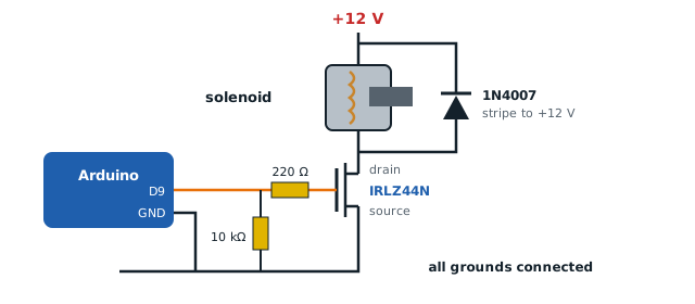
The Arduino switches a logic-level MOSFET, the MOSFET switches the solenoid's ground side, and a diode across the coil absorbs the voltage spike when it turns off.
| From | To |
|---|---|
| +12 V supply | solenoid wire 1 |
| solenoid wire 2 | MOSFET drain |
| MOSFET source | GND |
| Arduino pin 9 | 220 Ω → MOSFET gate |
| MOSFET gate | 10 kΩ → GND (pull-down) |
| Diode 1N4007 | across the solenoid, stripe (cathode) toward +12 V |
| Supply GND | Arduino GND |
Use a logic-level MOSFET such as the IRLZ44N or IRL540N, which turns fully on with 5 V on the gate. The common IRFZ44N is not logic level. All of this is explained in more depth in controlling a DC motor with a transistor.
Why the diode is essential
A coil stores energy in its magnetic field. When the MOSFET switches off, that energy has to go somewhere, and the coil produces a voltage spike that can reach hundreds of volts. Without a diode, it destroys the MOSFET, sometimes on the first click. The diode gives the current a safe loop to circulate in until it dies out.
A relay module would also work (see relay modules), but a MOSFET is silent, faster and can do the PWM trick below.
Basic code: a quick tap
const int SOL_PIN = 9;

void tap(unsigned long ms) {
  digitalWrite(SOL_PIN, HIGH);
  delay(ms);
  digitalWrite(SOL_PIN, LOW);
}

void setup() {
  pinMode(SOL_PIN, OUTPUT);
  digitalWrite(SOL_PIN, LOW);
}

void loop() {
  tap(80);        // short pulse is enough to pull the plunger in
  delay(1000);
}
Pulses of 30–100 ms are usually enough for a tap or a strike.
The duty-cycle rule (why solenoids burn)
Most cheap solenoids are rated for intermittent duty. The coil is designed to be on only part of the time, for example 25 % duty and a few seconds maximum. Leave a 12 V lock powered for minutes and it gets very hot, and the insulation can fail.
Check the datasheet. If it doesn't say "continuous duty" or "100 %", assume it isn't.
The PWM hold trick
A solenoid needs a lot of current to pull the plunger in, but much less to hold it once it's closed, because the magnetic gap is smaller. So: full power for a moment, then reduce it with PWM:
const int SOL_PIN = 9;   // PWM pin

void openLatch(unsigned long holdMs) {
  analogWrite(SOL_PIN, 255);   // full power to pull in
  delay(150);
  analogWrite(SOL_PIN, 90);    // about 35 % to hold
  delay(holdMs);
  analogWrite(SOL_PIN, 0);     // release
}

void setup() {
  pinMode(SOL_PIN, OUTPUT);
}

void loop() {
  openLatch(3000);
  delay(5000);
}
Find the lowest hold value that still holds reliably for your solenoid, then add a little margin. This can cut the heat by more than half. The diode is even more important here, because it carries current on every PWM cycle. You may hear a faint whine; that's the PWM frequency in the coil and is harmless.
Powering it
- Use a supply that matches the solenoid's voltage and can deliver its current with margin. A 12 V, 2 A adapter is fine for most single locks.
- Add a 470–1000 µF capacitor across the supply near the solenoid if the Arduino resets when it fires.
- If the Arduino runs from the same 12 V supply, feed it through the barrel jack or a buck converter, never the 5 V pin. See how to power an Arduino project.
Ideas
- Swap the servo latch in the RFID door lock for a 12 V solenoid lock.
- Make a robotic drum: a solenoid tapping a box, triggered from a rhythm array in code.
- A water valve for the automatic plant watering system.
Troubleshooting
- Solenoid buzzes but doesn't pull in: not enough voltage or current, or the plunger is loaded too heavily. Check the supply under load with a multimeter.
- MOSFET gets hot: it's not logic level, or the gate resistor/pull-down is wired wrong.
- MOSFET died instantly: missing or reversed diode. The stripe goes to the positive side.
- Solenoid very hot: it's on too long. Shorten the on-time or use the PWM hold.
— TheSolderBench · found a mistake? tell me