Log #49 · Oct 8, 2026
What Is PWM? Pulse Width Modulation Explained
How PWM fakes an analog voltage by switching fast, what duty cycle and frequency mean, and how Arduino's analogWrite() uses it to dim LEDs and control motors.
A microcontroller pin can only be fully on or fully off: 5 V or 0 V on an Arduino Uno. Yet the same pin can dim an LED smoothly or run a motor at half speed. The trick is pulse width modulation, or PWM: switching the pin on and off so fast that the device only notices the average. This guide explains how PWM works, the two numbers that describe it and how to use it well.
The idea: average power
Imagine flicking a light switch on and off ten times a second. The room flickers. Now imagine doing it thousands of times a second. Your eyes can no longer follow, and the light simply looks dimmer. If the switch is on half the time, the lamp delivers about half its power.
That is PWM. Instead of lowering the voltage, you control how much of the time the voltage is applied.
Duty cycle
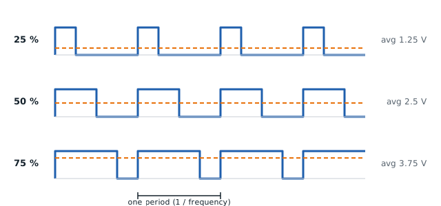
The duty cycle is the percentage of each cycle that the signal is high.
- 0 % → always off
- 25 % → on a quarter of the time
- 50 % → on half the time
- 100 % → always on
For a 5 V signal, the average voltage is simply:
V_avg = duty cycle × 5 V
So 25 % gives an average of 1.25 V and 75 % gives 3.75 V. The pin never actually sits at 1.25 V; it is always at 5 V or 0 V. A slow device (a motor, an LED seen by a human eye, a heater) responds to the average.
Frequency
The frequency is how many complete on-off cycles happen per second. It does not change the average, but it decides whether the switching is noticeable:
| Load | Typical PWM frequency | Why |
|---|---|---|
| LEDs | above ~200 Hz | Below that, flicker becomes visible, especially in peripheral vision or on camera |
| Small DC motors | 500 Hz – 20 kHz | Low frequencies cause audible whine; very high ones increase driver losses |
| Servos | 50 Hz, but the pulse width carries the position | A different use of pulses; see controlling a servo |
| Switching regulators | 50 kHz – 2 MHz | Small inductors need fast switching |
PWM on Arduino: analogWrite()
On an Uno or Nano, analogWrite(pin, value) produces PWM on the pins marked with a tilde (~): 3, 5, 6, 9, 10 and 11. The value goes from 0 to 255, so:
duty cycle = value ÷ 255
const int LED_PIN = 9;   // a PWM pin

void setup() {
  pinMode(LED_PIN, OUTPUT);
}

void loop() {
  for (int v = 0; v <= 255; v++) {   // fade up
    analogWrite(LED_PIN, v);
    delay(5);
  }
  for (int v = 255; v >= 0; v--) {   // fade down
    analogWrite(LED_PIN, v);
    delay(5);
  }
}
On the Uno, pins 5 and 6 run at about 980 Hz and the others at about 490 Hz. Both are fine for LEDs and most small motors. Despite its name, analogWrite() does not produce a true analog voltage on these boards; it is PWM. The difference between analog and digital pins is covered in digital vs analog pins.
Why LEDs don't look linear
If you set an LED to 50 % duty cycle, it looks much brighter than half. Human eyes perceive brightness roughly logarithmically, so equal steps in duty cycle look like big jumps at the dim end and almost nothing at the bright end. For smooth-looking fades, apply a simple gamma curve:
int gammaCorrect(int level) {          // level 0-255 as you "feel" it
  float x = level / 255.0;
  return (int)(pow(x, 2.2) * 255 + 0.5);
}
Write analogWrite(LED_PIN, gammaCorrect(v)) in the fade loop and the change looks even from start to finish.
Driving motors with PWM
An Arduino pin can only supply about 20 mA, far too little for a motor. PWM is used to switch a transistor or MOSFET that carries the motor current, or the enable pin of a motor driver. The motor's inertia smooths the pulses into a steady speed. Wiring, flyback diodes and code are in controlling DC motor speed with a transistor and PWM.
Turning PWM into a real voltage
Sometimes you need a genuine steady voltage, for example as a reference for another circuit. A simple RC low-pass filter (a resistor in series, then a capacitor to ground) averages the PWM signal. With 10 kΩ and 10 µF the ripple at 490 Hz is small, at the cost of a slow response (it takes about half a second to settle after a change). The output cannot drive any real load; buffer it with an op-amp if you need current.
Common mistakes
- Using a pin without a ~.
analogWrite()on a non-PWM pin acts like a plain on/off: values below 128 give LOW, the rest HIGH. - Expecting 2.5 V on a multimeter to mean anything. Many meters show the average, but some read nonsense on fast PWM. Use an oscilloscope to see the real waveform.
- Powering a motor directly from the pin. Always use a transistor or driver.
- Mixing PWM with certain libraries. The Servo library disables PWM on pins 9 and 10 on the Uno because it uses the same timer.
— TheSolderBench · found a mistake? tell me