Log #41 · Oct 3, 2026
Pull-Up and Pull-Down Resistors Explained
Why a button input floats, how pull-up and pull-down resistors fix it, which value to choose, and how to use the Arduino's built-in INPUT_PULLUP.
Wire a push button straight to an Arduino pin and the readings go crazy: the pin flips between HIGH and LOW even when nobody touches the button. Waving your hand near the wires can change it. Nothing is broken. The pin is floating, and the cure is a single resistor. This guide explains why it happens, how pull-up and pull-down resistors fix it, and how to choose the value.
Why an input pin floats
A digital input on a microcontroller has a very high impedance, in the range of megaohms. It barely draws any current; it only senses the voltage on the pin. That is great for not loading your circuit, but it means the pin needs something to define its voltage.
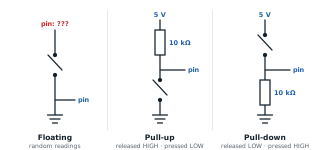
When the button is pressed, the pin is connected to 5 V or GND and the reading is clear. When the button is released, the pin is connected to nothing. A wire attached to nothing acts like a small antenna. It picks up mains hum, static from your hand and noise from nearby signals, and the voltage drifts anywhere between 0 and 5 V. The microcontroller reads that drifting voltage as a random mix of HIGH and LOW.
The fix: give the pin a default
A pull-up resistor connects the pin to the supply voltage. A pull-down resistor connects it to ground. Either way, when the button is open the resistor gently holds the pin at a known level. When the button closes, it connects the pin firmly to the opposite level and wins easily, because a closed switch has almost zero resistance.
Pull-up: button to ground
- Resistor from the pin to 5 V, button from the pin to GND.
- Released: the resistor pulls the pin up to 5 V → reads HIGH.
- Pressed: the button shorts the pin to GND → reads LOW.
The logic is "inverted": pressed equals LOW. It feels odd at first, but it is the most common arrangement in electronics.
Pull-down: button to 5 V
- Resistor from the pin to GND, button from the pin to 5 V.
- Released: the resistor pulls the pin down to 0 V → reads LOW.
- Pressed: the button connects the pin to 5 V → reads HIGH.
Pressed equals HIGH, which is more intuitive, but you need an external resistor because most Arduino boards have no built-in pull-downs.
Choosing the resistor value
When the button is pressed, current flows through the resistor from 5 V to GND. With Ohm's law:
| Resistor | Current when pressed (5 V) | Notes |
|---|---|---|
| 1 kΩ | 5 mA | Wastes current, very noise resistant |
| 10 kΩ | 0.5 mA | The standard choice for buttons |
| 47 kΩ | 0.1 mA | Good for battery projects, short wires |
| 1 MΩ | 5 µA | Too weak; noise can still sneak in |
The trade-off is simple. A smaller resistor holds the pin more firmly and resists noise better, but wastes more current while the button is pressed. A larger resistor saves power but holds the pin weakly. 10 kΩ is the sweet spot for almost every button and switch. For long wires (over a meter) in a noisy place, drop to 4.7 kΩ or 2.2 kΩ.
The built-in pull-up: INPUT_PULLUP
Arduino boards based on the ATmega328P (Uno, Nano) and most others have internal pull-up resistors of roughly 20–50 kΩ on every digital pin. You switch them on in code, so the button needs no external parts at all:
const int BUTTON_PIN = 2;
const int LED_PIN = 13;

void setup() {
  pinMode(BUTTON_PIN, INPUT_PULLUP);  // enable internal pull-up
  pinMode(LED_PIN, OUTPUT);
}

void loop() {
  bool pressed = digitalRead(BUTTON_PIN) == LOW;  // LOW means pressed
  digitalWrite(LED_PIN, pressed ? HIGH : LOW);
}
Wire one leg of the button to pin 2 and the other leg to GND. That is the whole circuit. This is why most Arduino button tutorials connect buttons to ground: it lets you use INPUT_PULLUP and skip the resistor.
The internal pull-up is weaker than a 10 kΩ external resistor, so for long cable runs or electrically noisy projects (motors, relays), add an external 10 kΩ pull-up as well.
Where else you will meet pull-ups
Pull-up resistors are not only for buttons:
- I²C buses (SDA and SCL lines, used by OLED displays, the MPU6050 and many sensors) need pull-ups because devices can only pull the lines low. Most breakout boards already include 4.7 kΩ or 10 kΩ pull-ups.
- Open-collector and open-drain outputs, such as some motion sensors and the alert pins of many chips, only switch to ground and need a pull-up to produce a HIGH.
- Reset pins on microcontrollers are held HIGH with a pull-up so the chip does not reset randomly.
- MOSFET gates: a pull-down resistor (often 10 kΩ to 100 kΩ) keeps a MOSFET off while the Arduino is booting and its pins are still floating. Without it, a motor can twitch at power-up.
Common mistakes
- Forgetting the resistor entirely. If a button reading is random or changes when you touch the wires, the pin is floating.
- Using
INPUTinstead ofINPUT_PULLUPwith a button wired to ground. The pin floats whenever the button is open. - Expecting HIGH when pressed with a pull-up. With a pull-up, pressed reads LOW. Flip the logic in code rather than rewiring.
- Tiny resistor values. A 100 Ω "pull-up" wastes 50 mA when the button is pressed, more than the pin should ever see if it is accidentally set as an output.
Once the pin is stable, you may still see a single press counted several times. That is switch bounce, a mechanical effect, and it is covered in reading a push button and debouncing it.
— TheSolderBench · found a mistake? tell me