Log #71 · Oct 15, 2026
Oscilloscope Basics for Beginners (Your First Measurements)
What an oscilloscope shows that a multimeter can't, the three groups of controls (volts, time, trigger), probe setup and compensation, a first measurement of Arduino PWM, and how to choose a first scope.
A multimeter tells you a number: 3.3 V, 20 mA. An oscilloscope shows you a picture: how a voltage changes over time. That's how you see a PWM signal, a noisy power supply, a servo pulse or a bouncing button. Scopes look intimidating, but almost everything comes down to three controls.
What the screen shows
The screen is a graph:
- Vertical axis = voltage. Each grid square is set by the volts per division (V/div) knob.
- Horizontal axis = time. Each grid square is set by the time per division (s/div) knob.
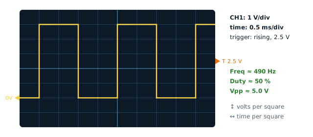
So with 1 V/div and 1 ms/div, a signal that rises 5 squares and repeats every 2 squares is a 5 V signal at 500 Hz.
The three control groups
1. Vertical (volts) - V/div: zoom the signal up or down. - Position: move the trace up or down on the screen. - Coupling: DC shows the full voltage; AC removes the average so you can zoom into small ripple riding on top of a DC voltage.
2. Horizontal (time) - s/div: stretch or squeeze time. Fast signals need small values like µs/div. - Position: slide the picture left or right.
3. Trigger (makes the picture stand still) Without a trigger, a repeating signal scrolls across the screen as a blur. The trigger tells the scope: start drawing each time the signal crosses this voltage in this direction. - Level: set it about halfway up your signal. - Edge: rising or falling. - Mode: Auto (always draws, good for finding a signal), Normal (draws only when triggered), Single (captures one event and freezes, perfect for a button press or a startup glitch).
If the picture won't stay still, the trigger is the first thing to check.
Probes: 1× vs 10×, and compensation
Most probes have a 1×/10× switch.
- 10× is the normal setting: it reduces the voltage by 10 inside the probe, loads your circuit less and gives much better high-frequency response. Set the scope's channel to 10× too, so the numbers on screen are right.
- 1× is only for very small, slow signals.
Compensate the probe once: connect it to the scope's built-in calibration output (a square wave, often 1 kHz, 3–5 V) and look at the corners. Turn the small screw on the probe until the square wave has flat tops: not rounded (under-compensated), not with spikes (over-compensated).
Safety: the ground clip
On a mains-powered bench scope, the probe's ground clip is connected to earth through the power cord. Connect it only to the ground of your circuit. Clipping it to any other point of a mains-connected circuit creates a short through the scope. For Arduino and battery projects there's no risk, but never measure mains-powered circuits without proper training and isolation.
Your first measurement: Arduino PWM
Upload this to an Uno or Nano:
void setup() {
  pinMode(9, OUTPUT);
  analogWrite(9, 128);    // about 50 % duty
}

void loop() {}
- Probe set to 10×, channel set to 10×, DC coupling.
- Ground clip to Arduino GND, probe tip to pin 9.
- Set 1 V/div and 0.5 ms/div.
- Trigger: rising edge, level about 2.5 V, mode Auto.
- You should see a square wave about 5 squares tall with a period of about 2 ms (≈490 Hz).
- Press Measure (or Auto) and turn on frequency and duty cycle.
Now change 128 to 32 and 224 and watch the duty cycle change. That's PWM in action.
More things worth looking at
- Servo pulses: 1–2 ms wide, repeating every 20 ms. Use 5 ms/div. See how to control a servo.
- Button bounce: single-trigger on a falling edge at 100 µs/div and press the button. You'll see the bouncing that debouncing fixes.
- Power-supply ripple: AC coupling, 20–50 mV/div, on the output of a buck converter.
- Serial data: many digital scopes can decode UART, I²C and SPI and show the bytes on screen.
Choosing a first scope
| Type | Bandwidth | Good for |
|---|---|---|
| DSO138-style kits | ~200 kHz, 1 channel | Learning, audio, slow PWM; very limited |
| Pocket/handheld scopes | 1–10 MHz | Portable checks, field work |
| Entry bench scopes (2–4 channels) | 50–100 MHz | Everything in hobby electronics, including I²C and SPI |
Rule of thumb: for square waves, choose a bandwidth at least 5 times the signal frequency. A 50–100 MHz, two-channel bench scope covers almost anything an Arduino or ESP32 does, and two channels let you compare, for example, a trigger pin and an echo pin at once.
Quick troubleshooting
- Flat line: wrong channel, V/div too large, or ground clip not connected.
- Blur that won't stop: trigger level outside the signal or wrong channel selected as trigger source.
- Voltage reads 10× too low or high: probe and channel settings don't match (1× vs 10×).
- Square wave has rounded corners or spikes: compensate the probe.
A scope doesn't replace a multimeter; you'll use both. See the rest of a good setup in electronics bench tools.
— TheSolderBench · found a mistake? tell me