Log #46 · Oct 3, 2026
How Two-Wheel Robots Turn (Differential Drive Made Simple)
The simple math behind differential drive robots: how wheel speeds set the turning radius, spin and pivot turns, smooth arcs in code, and basic odometry.
Most hobby robots, and a lot of real ones, steer the same way a tank does: there is no steering wheel, just two driven wheels, one on each side. Make them turn at different speeds and the robot curves. This layout is called differential drive, and with two short formulas you can make it follow precise arcs, turn on the spot and track its own position. This guide explains the idea with as little math as possible.
The basic idea
Picture the robot from above. The two wheels sit on the same axle line, a distance W apart (the track width). Each wheel rolls forward at its own speed: vL for the left and vR for the right.
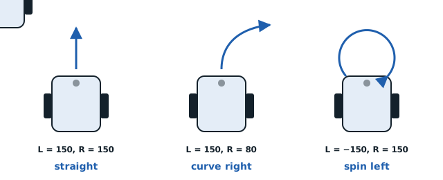
- Same speed, same direction: the robot drives straight.
- Right faster than left: the robot curves to the left.
- Same speed, opposite directions: the robot spins on the spot around its center.
- One wheel stopped: the robot pivots around that stopped wheel.

The two formulas
The robot's forward speed is the average of the two wheels:
v = (vR + vL) ÷ 2
Its turning rate (how fast its heading changes, in radians per second) depends on the difference:
ω = (vR − vL) ÷ W
Put them together and you get the turning radius, the distance from the robot's center to the point it circles around:
R = v ÷ ω = (W ÷ 2) × (vR + vL) ÷ (vR − vL)
Check the special cases. Equal speeds make the bottom zero, so the radius is infinite: a straight line. Opposite speeds make the top zero, so the radius is zero: a spin on the spot. One wheel stopped gives R = W ÷ 2: the robot circles around the stopped wheel.
A worked example
A robot with W = 130 mm, and you want it to follow a circle with a 300 mm radius at a forward speed of 200 mm/s.
- ω = v ÷ R = 200 ÷ 300 ≈ 0.667 rad/s
- vR = v + ω × W ÷ 2 = 200 + 0.667 × 65 ≈ 243 mm/s
- vL = v − ω × W ÷ 2 = 200 − 43 ≈ 157 mm/s
So the outer wheel runs about 55 % faster than the inner one. Those last two lines are the useful ones in code: pick the speed and turn rate you want, and they give you each wheel's speed.
Spin turns vs pivot turns
Spin turn (wheels opposite): the robot rotates around its own center and stays in place. Best for tight spaces and for "turn 90° then continue" maneuvers, like the obstacle-avoiding robot.
Pivot turn (one wheel stopped): the robot swings around the stopped wheel. It needs more space and puts more load on the moving motor, but some robots use it because a stopped motor holds position better than a slow one.
For a spin turn of angle θ (in radians), each wheel travels an arc of θ × W ÷ 2. A 90° turn (π/2) with W = 130 mm means each wheel moves about 102 mm. With encoders you can count that distance exactly; see adding wheel encoders to a robot.
Turning the math into code
Motor drivers take a PWM value, not millimeters per second. For a first version, treat PWM as roughly proportional to speed and scale with a constant you find by testing:
// Motor driver pins (TB6612FNG or L298N)
const int PWMA = 5, AIN1 = 7, AIN2 = 8;   // left motor
const int PWMB = 6, BIN1 = 9, BIN2 = 10;  // right motor

const float TRACK_MM = 130.0;      // distance between wheels
const float PWM_PER_MM_S = 0.8;    // found by testing your robot

void setMotor(int pwmPin, int in1, int in2, float speed) {
  int pwm = constrain(abs(speed) * PWM_PER_MM_S, 0, 255);
  digitalWrite(in1, speed >= 0);
  digitalWrite(in2, speed < 0);
  analogWrite(pwmPin, pwm);
}

// v: forward speed in mm/s, w: turn rate in rad/s (positive = left)
void drive(float v, float w) {
  float vL = v - w * TRACK_MM / 2;
  float vR = v + w * TRACK_MM / 2;
  setMotor(PWMA, AIN1, AIN2, vL);
  setMotor(PWMB, BIN1, BIN2, vR);
}

void setup() {
  int pins[] = {PWMA, AIN1, AIN2, PWMB, BIN1, BIN2};
  for (int p : pins) pinMode(p, OUTPUT);
}

void loop() {
  drive(200, 0);      delay(1500);   // straight
  drive(200, 0.667);  delay(3000);   // arc, radius ~300 mm
  drive(0, 2.0);      delay(800);    // spin in place
  drive(0, 0);        delay(2000);   // stop
}
If you use a TB6612FNG, remember to pull its STBY pin HIGH. The wiring for both common drivers is in motor drivers: L298N vs TB6612.
To find PWM_PER_MM_S, drive straight at a fixed PWM for two seconds, measure the distance with a tape, and divide. Real motors are not perfectly linear, especially near their minimum speed, so test at the speeds you plan to use.
Why the robot still drifts
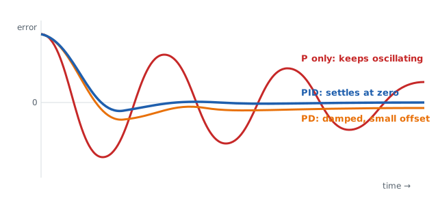
Even with perfect math, two "identical" motors rarely match. One runs a few percent faster, and the robot curves. Floors, battery voltage and wheel slip add more error. The fix is feedback: measure each wheel's real speed with encoders and correct it with a control loop. A proportional correction is often enough to drive straight; a full PID loop holds each wheel at its target speed under changing load.
Odometry: where am I?
If you know how far each wheel moved since the last update (dL and dR, from encoders), you can update the robot's position:
float x = 0, y = 0, heading = 0;   // mm, mm, radians

void updateOdometry(float dL, float dR) {
  float d = (dL + dR) / 2;             // distance traveled by the center
  float dTheta = (dR - dL) / TRACK_MM; // change in heading
  heading += dTheta;
  x += d * cos(heading);
  y += d * sin(heading);
}
Call it many times per second and the robot keeps a running estimate of its position. Small errors accumulate, so odometry drifts over long distances, but it is accurate enough for moving a meter or two and returning near the start. Adding a gyroscope like the MPU6050 to measure heading directly makes it much better.
Choosing your chassis
The math assumes the wheels sit on one axle line with a free caster for balance. Two-wheel-drive kits with a caster ball fit perfectly. Four-wheel "skid steer" chassis also steer differentially but drag their wheels sideways when turning, so they need more power and turn less predictably. Compare the options in the robot chassis guide.
— TheSolderBench · found a mistake? tell me