Log #102 · Nov 9, 2026
Robot Odometry: Tracking Position with Wheel Encoders
How a two-wheeled robot can estimate its x, y position and heading from wheel encoder ticks. The odometry equations step by step, Arduino code that updates the pose, how to calibrate wheel size and track width, and why the error grows.
A robot that knows how far each wheel has turned can work out where it is, without GPS, cameras or beacons. This is called odometry (or dead reckoning, the same idea sailors used with a compass and a log line). It's how a small robot drives an exact square, returns to its starting point, or knows it has traveled 2 meters down a corridor. This guide builds odometry for a two-wheeled robot step by step, using the encoders from wheel encoders for robots.
The idea
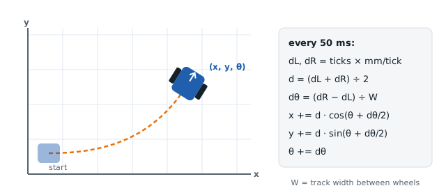
Every few milliseconds, the robot asks: how far did each wheel move since last time?
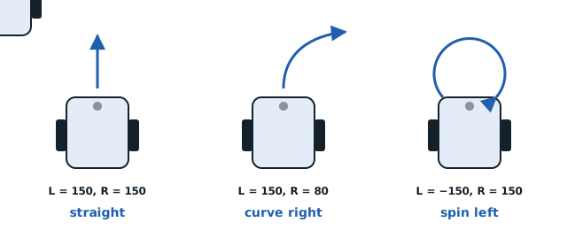
- If both wheels moved the same distance, the robot went straight.
- If the right wheel moved further, the robot curved to the left.
- If they moved in opposite directions, it turned in place.
From those two small distances you can compute how far the center of the robot moved and how much its heading changed. Adding up thousands of tiny steps gives the current position. The geometry of turning with two wheels is explained in how differential drive robots turn.
What you need to know about your robot
| Value | Symbol | How to get it |
|---|---|---|
| Encoder ticks per wheel revolution | N | Encoder slots × gear ratio (if the encoder is on the motor) |
| Wheel diameter | D | Measure, then calibrate |
| Track width (distance between wheel centers) | W | Measure, then calibrate |
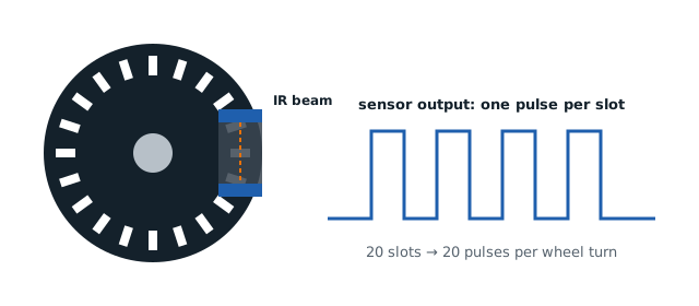
From these: distance per tick = π × D ÷ N. For a 65 mm wheel with a 20-slot encoder disc on the wheel shaft, that's π × 65 ÷ 20 ≈ 10.2 mm per tick.
The equations
Each update, read the ticks since the last update for each wheel and convert them to distances dL and dR. Then:
- Center distance: d = (dL + dR) ÷ 2
- Heading change (radians): dθ = (dR − dL) ÷ W
- Update position, using the heading halfway through the move:
- x = x + d × cos(θ + dθ ÷ 2)
- y = y + d × sin(θ + dθ ÷ 2)
- Update heading: θ = θ + dθ
That's the whole algorithm. Using the halfway heading in step 3 makes curves much more accurate than using the old heading.
Units: if D and W are in millimeters, x and y come out in millimeters and θ in radians (multiply by 57.3 for degrees). θ = 0 means the robot faces along the x axis, and positive θ is a left (counterclockwise) turn.
The code
This example uses single-channel encoders (one slotted disc and optical sensor per wheel) on interrupt pins 2 and 3. A single channel can't tell direction, so the code uses the direction the motors are being driven. For a robot that never gets pushed backward by hand, that works well.
#include <math.h>

const int ENC_LEFT = 2, ENC_RIGHT = 3;
const float TICKS_PER_REV = 20.0;
const float WHEEL_D = 65.0;          // mm, calibrate
const float TRACK_W = 130.0;         // mm, calibrate
const float MM_PER_TICK = M_PI * WHEEL_D / TICKS_PER_REV;

volatile long ticksL = 0, ticksR = 0;
int dirL = 1, dirR = 1;              // +1 forward, -1 backward: set where you drive the motors

float x = 0, y = 0, theta = 0;       // mm, mm, radians
long lastL = 0, lastR = 0;
unsigned long lastUpdate = 0;

void onLeft()  { ticksL++; }
void onRight() { ticksR++; }

void updateOdometry() {
  noInterrupts();
  long l = ticksL, r = ticksR;
  interrupts();

  float dL = (l - lastL) * MM_PER_TICK * dirL;
  float dR = (r - lastR) * MM_PER_TICK * dirR;
  lastL = l;
  lastR = r;

  float d = (dL + dR) / 2.0;
  float dTheta = (dR - dL) / TRACK_W;
  x += d * cos(theta + dTheta / 2.0);
  y += d * sin(theta + dTheta / 2.0);
  theta += dTheta;

  if (theta > M_PI) theta -= 2 * M_PI;      // keep heading between -180° and 180°
  if (theta < -M_PI) theta += 2 * M_PI;
}

void setup() {
  pinMode(ENC_LEFT, INPUT_PULLUP);
  pinMode(ENC_RIGHT, INPUT_PULLUP);
  attachInterrupt(digitalPinToInterrupt(ENC_LEFT), onLeft, FALLING);
  attachInterrupt(digitalPinToInterrupt(ENC_RIGHT), onRight, FALLING);
  Serial.begin(115200);
}

void loop() {
  if (millis() - lastUpdate >= 50) {         // 20 updates per second
    lastUpdate = millis();
    updateOdometry();
    Serial.print("x: ");
    Serial.print(x, 0);
    Serial.print(" mm  y: ");
    Serial.print(y, 0);
    Serial.print(" mm  heading: ");
    Serial.print(theta * 180.0 / M_PI, 1);
    Serial.println(" deg");
  }
  // your driving code goes here; set dirL/dirR whenever motor direction changes
}
Push the robot by hand in a straight line (with dirL and dirR at +1) and x should grow while y and heading stay near zero. Then pivot it to the left around the left wheel (hold the left wheel still and push the right wheel forward): the heading should rise. A spin in place only reads correctly when your driving code sets dirL = -1 for the wheel turning backward.
Encoder noise: cheap slotted-disc sensors can produce extra counts from vibration at the edge of a slot. If ticks increase while the wheel is still, add a small capacitor (10–100 nF) from the sensor output to ground, or use modules with a Schmitt-trigger comparator. Quadrature encoders (two channels) remove the direction guesswork entirely, as explained in the rotary encoder guide.
Calibrating
Measured values are never exact: tires compress, and the contact point isn't exactly in the middle of the tire. Two simple tests fix most of the error.
1. Wheel diameter (distance):
- Mark the start, drive (or push) the robot straight for exactly 2 m, measured with a tape.
- Read x from the Serial Monitor.
- Correct: new D = old D × (real distance ÷ measured x).
2. Track width (turning):
- Mark the robot's heading with a line on the floor.
- Spin the robot in place exactly 10 full turns (3600°), stopping where it started.
- Read the total heading change. The code wraps θ at ±180°, so for this test temporarily comment out the two wrap lines and print θ in degrees.
- Correct: new W = old W × (measured degrees ÷ 3600).
If the robot reports too many degrees, the real track is wider than the value in the code, and vice versa. Ten turns make a small error easy to measure.
Why the error grows
Odometry is never perfect, and its errors add up:
- Wheel slip on smooth floors, during fast starts or sharp turns: the wheel turns but the robot doesn't move as far.
- Uneven floors, carpets and bumps.
- Small calibration errors in W, which hurt most: a 1 % error in track width becomes a 3.6° heading error per full turn, and every following meter of travel drifts sideways.
- Encoder resolution: 20 ticks per revolution is coarse; more ticks means smoother estimates.
Expect a well-calibrated small robot to be within a few centimeters after a few meters of driving. After many turns, the position slowly drifts. That's why real robots combine odometry with other sensors: an IMU for heading, distance sensors to detect walls, or line markers on the floor to reset the position.
Using the position
Once you know x, y and θ, you can:
- Drive an exact distance: note the start point (x0, y0), then move forward until √((x − x0)² + (y − y0)²) reaches the target.
- Turn to a heading: spin until θ reaches the desired angle, ideally with a PID controller to slow down near the target.
- Return home: compute the angle to (0, 0) with
atan2(-y, -x), turn to it, and drive the distance √(x² + y²). - Draw the path: print x and y and plot them in a spreadsheet to see how the robot moved.
Troubleshooting
- Heading changes while driving straight: the two wheels have slightly different diameters or one encoder misses ticks. Calibrate each wheel separately (separate mm-per-tick values) if needed.
- Heading goes the wrong way: swap the left and right encoder pins.
- Distance always short: wheel slip. Accelerate gently and use grippier tires.
- Values jump while stopped: encoder noise; see the capacitor tip above.
— TheSolderBench · found a mistake? tell me