Log #81 · Oct 26, 2026
Transistors Explained: Using an NPN Transistor as a Switch
How a bipolar transistor works as an electronic switch, how to wire an NPN like the 2N2222 or BC547 to an Arduino, how to calculate the base resistor, and when to use a MOSFET instead.
An Arduino pin can only supply about 20 mA. A relay coil, a buzzer, a strip of LEDs or a small motor needs more. The classic fix costs a few cents: a transistor used as a switch. The Arduino controls a tiny current, and the transistor switches the big one.
What a bipolar transistor does
An NPN transistor has three legs:
- Base (B): the control input.
- Collector (C): where the load current comes in.
- Emitter (E): where it goes out, usually to GND.
A small current flowing into the base lets a much larger current flow from collector to emitter. The ratio between the two is the current gain, called hFE or β, typically 100–300 for small transistors. So 1 mA into the base can allow 100 mA or more through the load.
Used as a switch, the transistor has two states:
- Off: no base current, no load current. The load is off.
- On (saturated): enough base current that the transistor is fully on. Only about 0.2 V is left across it, and the load gets almost the full supply voltage.
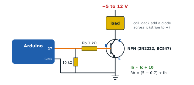
Wiring an NPN low-side switch
| Connection | Where it goes |
|---|---|
| Load + | the load's supply (5 V, 9 V, 12 V…) |
| Load − | transistor collector |
| Emitter | GND |
| Base | Arduino pin through a base resistor |
| 10 kΩ | from the Arduino pin to GND (optional, keeps the transistor off at reset) |
| GND | load supply GND and Arduino GND connected |
This is called a low-side switch because the transistor sits between the load and ground. It works for any load voltage up to the transistor's rating, as long as the grounds are shared.
Calculating the base resistor
- Find the load current (Ic). Example: a 5 V relay coil of 70 Ω draws 5 ÷ 70 ≈ 71 mA.
- For a reliable switch, give the base about 1/10 of the load current, regardless of hFE. This "forced gain" of 10 makes sure the transistor saturates even when it's a weak sample or warm. Ib ≈ 71 ÷ 10 ≈ 7 mA.
- The base drops about 0.7 V, so:
Rb = (Vpin − 0.7) ÷ Ib = (5 − 0.7) ÷ 0.007 ≈ 614 Ω → use 560 Ω (the next standard value down, a little more current).
For small loads (under 50 mA), 1 kΩ is a safe default on a 5 V Arduino. Check that the base current stays under about 20 mA, the comfortable limit for an Arduino pin. The math is just Ohm's law.
Common small NPN transistors
| Part | Max collector current | Max voltage | Notes |
|---|---|---|---|
| BC547 | 100 mA | 45 V | Tiny loads: LEDs, small buzzers |
| 2N3904 | 200 mA | 40 V | General purpose |
| 2N2222A / PN2222A | 600 mA | 40 V (30 V for plain 2N2222) | Relays, small motors, LED groups |
| TIP120 (Darlington) | 5 A | 60 V | Big loads, but drops 1–2 V |
Stay well below the maximums: around half the rated current is a good working limit.
Check the pinout in the datasheet. It differs between parts: a BC547 is usually C-B-E and a PN2222A E-B-C (flat face toward you, legs down), and some manufacturers swap them. A transistor wired backwards works badly or not at all. See how to read a datasheet.
Example: switching a 12 V LED strip segment
const int SWITCH_PIN = 7;   // to the base resistor

void setup() {
  pinMode(SWITCH_PIN, OUTPUT);
}

void loop() {
  digitalWrite(SWITCH_PIN, HIGH);   // transistor on, load on
  delay(1000);
  digitalWrite(SWITCH_PIN, LOW);    // transistor off, load off
  delay(1000);
}
A short segment drawing 150 mA from 12 V needs about 15 mA of base current: Rb = (5 − 0.7) ÷ 0.015 ≈ 287 Ω → 270 Ω. A 2N2222 handles it easily. You can also dim it with analogWrite(), since transistors switch fast enough for PWM.
Inductive loads need a diode
Relays, motors, solenoids and buzzers with coils produce a voltage spike when switched off. Put a diode (1N4007 or 1N4148) across the load, with its stripe toward the positive supply. Without it, the spike can destroy the transistor. Why this works is explained in diodes explained, and the same rule appears in the relay module guide.
PNP transistors: switching the high side
A PNP transistor works the other way round: it sits between the supply and the load, and turns on when its base is pulled lower than its emitter. PNP high-side switches are handy when the load must share ground with something else, but driving them from a 5 V Arduino is only simple when the load supply is also 5 V. For beginners, the NPN low-side switch is the one to learn first.
Transistor or MOSFET?
| NPN bipolar | Logic-level MOSFET | |
|---|---|---|
| Controlled by | current into the base | voltage on the gate |
| Needs | a base resistor sized for the load | a small gate resistor and a pull-down |
| Voltage lost when on | about 0.2 V (1–2 V for Darlingtons) | often well under 0.1 V |
| Best for | small loads up to a few hundred mA | anything from small loads to several amps |
For motors and anything above about half an amp, a logic-level MOSFET like the IRLZ44N runs cooler. That setup is covered in controlling a DC motor with a transistor and PWM.
Troubleshooting
- Load never turns on: transistor pinout reversed, or the grounds aren't connected.
- Load is dim or the transistor gets hot: not enough base current. Lower the base resistor.
- Transistor died when a relay switched off: missing flyback diode.
- Load is always on: collector and emitter swapped, or the transistor is shorted.
— TheSolderBench · found a mistake? tell me