Log #80 · Oct 19, 2026
Build a Temperature-Controlled Fan with Arduino (DS18B20 + MOSFET)
A fan that speeds up as it gets warmer: DS18B20 sensor, logic-level MOSFET and PWM speed control, with a fan curve, hysteresis, kick-start, silent 31 kHz PWM and a fail-safe. Full wiring and code.
This project makes a 12 V fan run only when it's needed and only as fast as it's needed: off when the room or enclosure is cool, gently spinning as it warms up, and full speed when it's hot. It's useful for a 3D printer enclosure, a TV cabinet, an amplifier, a box of electronics or a reptile terrarium. It also brings together several skills: a digital temperature sensor, a MOSFET switch, PWM and some good control habits.
Parts list
| Part | Notes |
|---|---|
| Arduino Uno or Nano | |
| DS18B20 temperature sensor | TO-92 package or the waterproof probe version |
| 4.7 kΩ resistor | Pull-up for the sensor's data line |
| 12 V DC fan, 2-wire | 80–120 mm PC fans are ideal; up to about 0.5 A |
| IRLZ44N logic-level MOSFET | |
| 1N5819 Schottky diode | Flyback protection; fast enough for 31 kHz PWM |
| 220 Ω and 10 kΩ resistors | Gate resistor and pull-down |
| 12 V, 1 A power adapter | Powers the fan and the Arduino |
Wiring
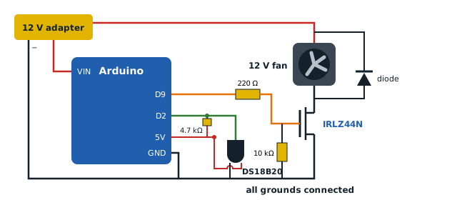
Fan and MOSFET (the same low-side switch as in controlling a DC motor with a transistor):
| From | To |
|---|---|
| 12 V + | fan red (+) and Arduino VIN |
| Fan black (−) | MOSFET drain |
| MOSFET source | GND |
| Arduino pin 9 | 220 Ω → MOSFET gate |
| Gate | 10 kΩ → GND |
| Diode 1N5819 | across the fan, stripe to +12 V |
DS18B20 (flat face toward you, pins left to right):
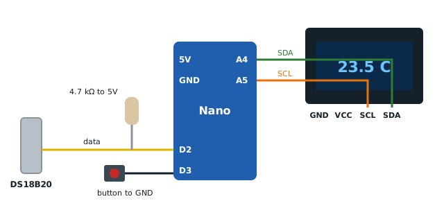
| DS18B20 pin | Arduino |
|---|---|
| GND (left) | GND |
| DQ, data (middle) | pin 2, plus 4.7 kΩ to 5 V |
| VDD (right) | 5 V |
The waterproof probe uses wire colors instead: usually red = VDD, black = GND, yellow (or white) = data. Why the pull-up is needed is explained in pull-up resistors; the sensor itself is compared with others in temperature sensors compared.
Libraries
Install OneWire (by Paul Stoffregen) and DallasTemperature (by Miles Burton) from the Library Manager.
The code
#include <OneWire.h>
#include <DallasTemperature.h>

const int ONE_WIRE_PIN = 2;
const int FAN_PIN = 9;            // Timer1 PWM pin

// Fan curve (°C)
const float T_ON  = 26.0;         // fan starts at this temperature
const float T_OFF = 25.0;         // and stops below this one (hysteresis)
const float T_MAX = 35.0;         // full speed at and above this
const int MIN_DUTY = 90;          // slowest reliable speed (0-255)
const int MAX_DUTY = 255;

OneWire oneWire(ONE_WIRE_PIN);
DallasTemperature sensors(&oneWire);

bool fanOn = false;
int currentDuty = 0;
unsigned long lastRead = 0;

void setFan(int duty) {
  if (duty > 0 && currentDuty == 0) {
    analogWrite(FAN_PIN, 255);    // kick-start a stopped fan
    delay(300);
  }
  analogWrite(FAN_PIN, duty);
  currentDuty = duty;
}

void setup() {
  Serial.begin(9600);
  // Raise PWM on pins 9 and 10 to about 31 kHz: no audible whine
  TCCR1B = (TCCR1B & 0b11111000) | 0x01;
  pinMode(FAN_PIN, OUTPUT);
  sensors.begin();
  setFan(0);
}

void loop() {
  if (millis() - lastRead < 2000) return;   // read every 2 s
  lastRead = millis();

  sensors.requestTemperatures();
  float t = sensors.getTempCByIndex(0);

  if (t == DEVICE_DISCONNECTED_C) {          // fail-safe
    Serial.println("Sensor error: fan to full speed");
    setFan(MAX_DUTY);
    return;
  }

  if (!fanOn && t >= T_ON)  fanOn = true;
  if (fanOn  && t <= T_OFF) fanOn = false;

  int duty = 0;
  if (fanOn) {
    float x = (t - T_ON) / (T_MAX - T_ON);   // 0 at T_ON, 1 at T_MAX
    x = constrain(x, 0.0, 1.0);
    duty = MIN_DUTY + x * (MAX_DUTY - MIN_DUTY);
  }
  if (duty != currentDuty) setFan(duty);

  Serial.print(t, 1);
  Serial.print(" C  -> duty ");
  Serial.println(duty);
}
How it works
- Fan curve: below 26 °C the fan is off. From 26 °C to 35 °C the speed rises in a straight line from
MIN_DUTYto full, then stays at full. Change the four constants to suit your use. - Hysteresis: the fan turns on at 26 °C but only turns off below 25 °C. Without that 1 °C gap, a temperature hovering at 26.0 would switch the fan on and off every few seconds.
- Minimum duty: most fans won't spin below about 30–40 % duty.
MIN_DUTY = 90(≈35 %) is a typical starting point. Lower it until your fan barely keeps turning, then add a little. - Kick-start: a stopped fan needs a push to start at low speed, so
setFan()gives it 300 ms at full power first. - 31 kHz PWM: at the Uno's default 490 Hz, many fans whine. Changing Timer1's prescaler moves pins 9 and 10 above hearing range. It doesn't affect
millis()ordelay()(Timer0), but it does change the Servo library's timing, so don't combine it with servos. At this frequency the MOSFET switches 31,000 times a second; with a small fan the 220 Ω gate resistor is fine, but for bigger fans a 100 Ω resistor keeps the MOSFET cooler. More about PWM frequency in PWM explained. - Fail-safe: if the sensor is unplugged or broken, the library returns −127 °C. A careless sketch would read that as "cold" and turn the fan off, exactly when you can't tell how hot it is. This one runs the fan at full speed instead.
4-pin PC fans
A 4-pin PC fan has a dedicated PWM input (blue wire) designed for about 25 kHz. You can keep the fan on constant 12 V and drive the blue wire directly from pin 9 (with the 31 kHz setting), with no MOSFET needed. Leave the fan's power wiring and grounds shared as usual. Note that most 4-pin fans don't stop at 0 % PWM; they keep turning slowly. If you need the fan fully off, keep the MOSFET in the power line as well.
Ideas to extend it
- Show the temperature and fan speed on an OLED, as in the OLED digital thermometer.
- Set
T_ONwith a rotary encoder and store it with EEPROM so it survives a power cut. - Read the tachometer wire of a 4-pin fan (powered at a constant 12 V) with an interrupt to show the real RPM and detect a stalled fan. With the low-side MOSFET used here, the fan's ground is switched on and off, which corrupts the tach signal.
Troubleshooting
- Temperature reads −127 °C: missing 4.7 kΩ pull-up or wrong pin order.
- Temperature reads 85 °C: the sensor's power-on value; it means a conversion didn't finish. Check power and wiring.
- Fan never stops: the MOSFET is damaged (shorted), its gate/drain/source pins are swapped, or the fan is wired around the MOSFET instead of through it.
- Fan clicks or won't start at low speed: raise
MIN_DUTYor lengthen the kick-start. - MOSFET hot: check it's an IRLZ44N (not IRFZ44N) and the fan current is within your design.
— TheSolderBench · found a mistake? tell me