Log #65 · Oct 15, 2026
Voltage Dividers Explained (With Arduino Examples)
How two resistors scale a voltage down, the formula with worked examples, measuring a 12 V battery with Arduino, shifting 5 V signals to 3.3 V, and why a divider can't power anything.
A voltage divider is just two resistors in series, but it shows up everywhere: reading a battery voltage, connecting a 5 V module to a 3.3 V board, reading a light sensor, even inside every potentiometer. Once you understand it, a lot of circuits suddenly make sense.
How it works
Put two resistors in series between a voltage and ground. The same current flows through both, so each one drops a share of the voltage proportional to its resistance. Tap the point between them and you get a fraction of the input.
The formula
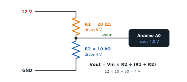
Vout = Vin × R2 ÷ (R1 + R2)
- R1 is the top resistor (between Vin and the output).
- R2 is the bottom resistor (between the output and GND).
It comes straight from Ohm's law: the current is Vin ÷ (R1 + R2), and the voltage across R2 is that current times R2. Because only the ratio matters, 1 kΩ + 2 kΩ gives the same output as 10 kΩ + 20 kΩ.
Worked examples
Halving a voltage: R1 = R2 = 10 kΩ. Vout = Vin × 10 ÷ 20 = Vin ÷ 2.
5 V to about 3.3 V: R1 = 1 kΩ, R2 = 2 kΩ. Vout = 5 × 2 ÷ 3 = 3.33 V. This is the classic way to protect the 3.3 V RX pin of a module like the HC-05, as in the Bluetooth robot car.
Choosing resistors for a target: you want 12.6 V (a full 3S Li-ion pack) to become at most about 4.2 V, safely under the Arduino's 5 V. Ratio = 4.2 ÷ 12.6 = 1/3, so R2 ÷ (R1 + R2) = 1/3 → R1 = 2 × R2. With R2 = 10 kΩ, R1 = 20 kΩ.
Measuring a battery with Arduino
The Arduino's analog pins can only read 0–5 V (or 0–3.3 V on 3.3 V boards). A divider lets you measure higher voltages:
const float R1 = 20000.0;   // top resistor, ohms
const float R2 = 10000.0;   // bottom resistor, ohms
const float VREF = 5.0;     // board voltage

void setup() {
  Serial.begin(9600);
}

void loop() {
  int raw = analogRead(A0);
  float vPin = raw * VREF / 1023.0;
  float vBattery = vPin * (R1 + R2) / R2;
  Serial.print("Battery: ");
  Serial.print(vBattery, 2);
  Serial.println(" V");
  delay(1000);
}
Wiring: battery + → R1 → A0 → R2 → GND, and the battery's − must connect to Arduino GND. How analogRead() turns volts into numbers is explained in Arduino analogRead() explained.
For better accuracy, measure your resistors and the real 5 V with a multimeter and put those values in the code. A USB-powered "5 V" is often 4.8 V or so.
Picking the resistor values
The ratio sets the output, but the actual values matter too:
- Too small (say 100 Ω + 200 Ω): wastes current. 12 V across 300 Ω is 40 mA, and it drains batteries.
- Too large (say 1 MΩ + 2 MΩ): the Arduino's analog input needs to charge a tiny internal capacitor each reading, and a high-resistance source makes readings inaccurate. Keep the parallel combination of R1 and R2 below about 10 kΩ for the ATmega328P's ADC.
- A good middle ground: about 10 kΩ to 40 kΩ total. 20 kΩ + 10 kΩ draws only 0.4 mA from 12 V and reads accurately. If you need higher values to save battery, add a 100 nF capacitor from A0 to GND so the ADC has a charge reservoir to sample from.
Check the power too: P = V² ÷ R. 12 V across 30 kΩ is under 5 mW, nothing for a ¼ W resistor.
Why you can't power things with a divider
A divider's output only holds its value if almost no current is taken from it. Connect a load (a motor, a module, an LED) and that load acts like a resistor in parallel with R2, which pulls the output voltage way down. A 5 V → 3.3 V divider made of 1 kΩ + 2 kΩ can't run a 3.3 V sensor drawing 20 mA.
To make a lower supply voltage, use a regulator or a buck converter instead: see voltage regulators explained and the LM2596 buck converter.
Dividers you already use
- Potentiometers are adjustable dividers: the wiper is the middle point. See reading a potentiometer.
- LDR light sensors are dividers where one resistor changes with light. See light sensors with Arduino.
- Pull-up resistors with buttons form a divider with the button. See pull-up and pull-down resistors.
Level shifting with a divider: when it works
A divider works well for one-way, slow-to-medium signals going from 5 V down to 3.3 V, such as a UART TX line at 9600–115200 baud. It does not work in the other direction (3.3 V up to 5 V), and it's not suitable for bidirectional buses like I²C. For those, use a proper level shifter module.
Quick recap
- Vout = Vin × R2 ÷ (R1 + R2), taken across the bottom resistor.
- Only the ratio sets the voltage; the values set the current and accuracy.
- Great for measuring voltages and shifting signals down.
- Never use one as a power supply.
— TheSolderBench · found a mistake? tell me